|NewGate School Technology Consulting and Setup| |Raspberry Pi NAS| |Tennisball Air Cannon| |J-Pole Antenna| |Homemade 2×4 Desk| |Minecraft Wooden Chest| |Stocks| |Reverse Geocache| |Solar Powered Phone Charger| |Electronic Slot Game| |My First Trebuchet| |Dimmable Flashlight/Warning Device|
NewGate School Technology Consulting and Setup
Recently, my school, NewGate bought a larger and newer campus to try to expand all of its programs. This building used to be a cancer support center but was abandoned (bank repossession) following the bankruptcy of the occupying charity.
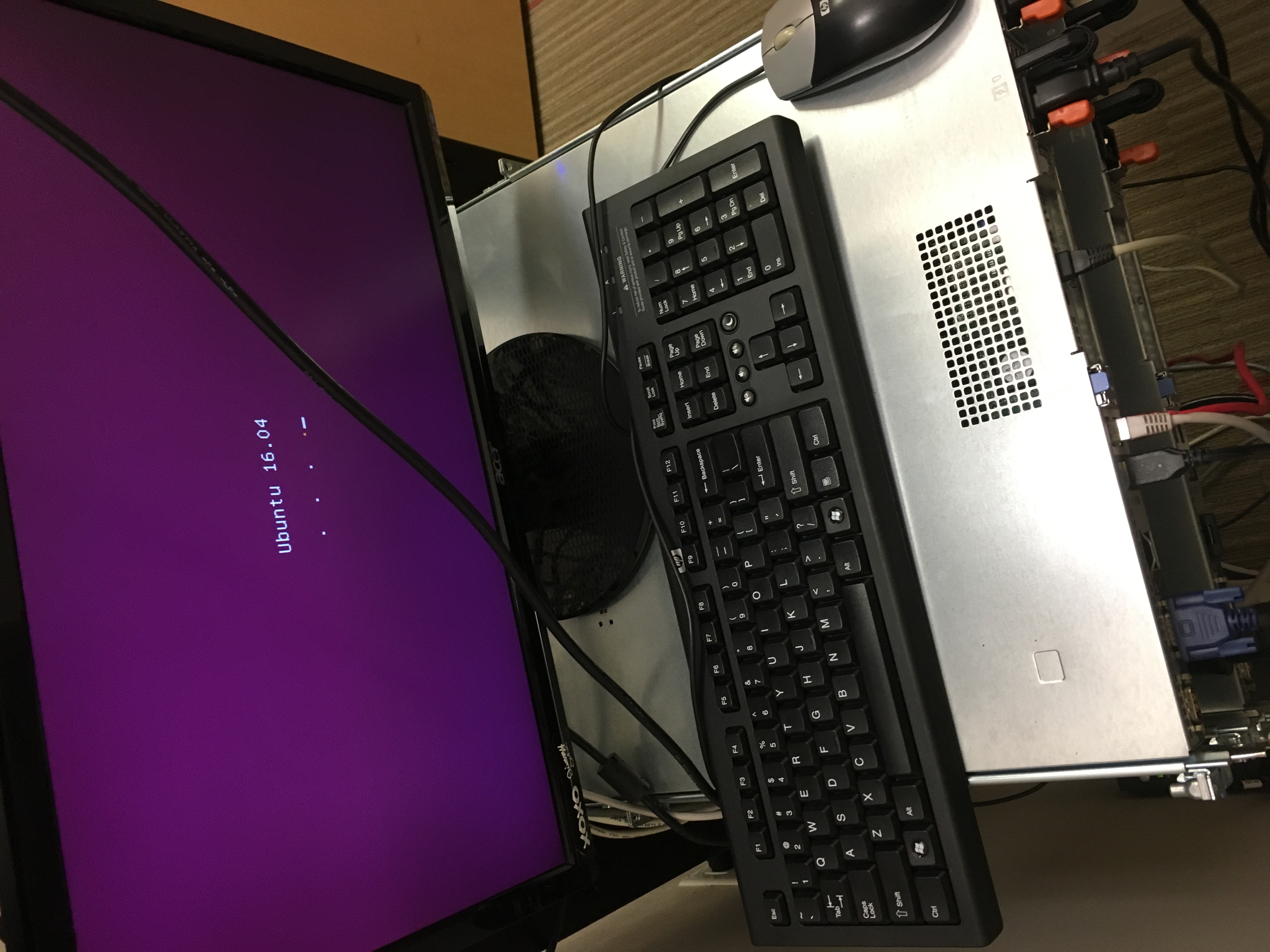
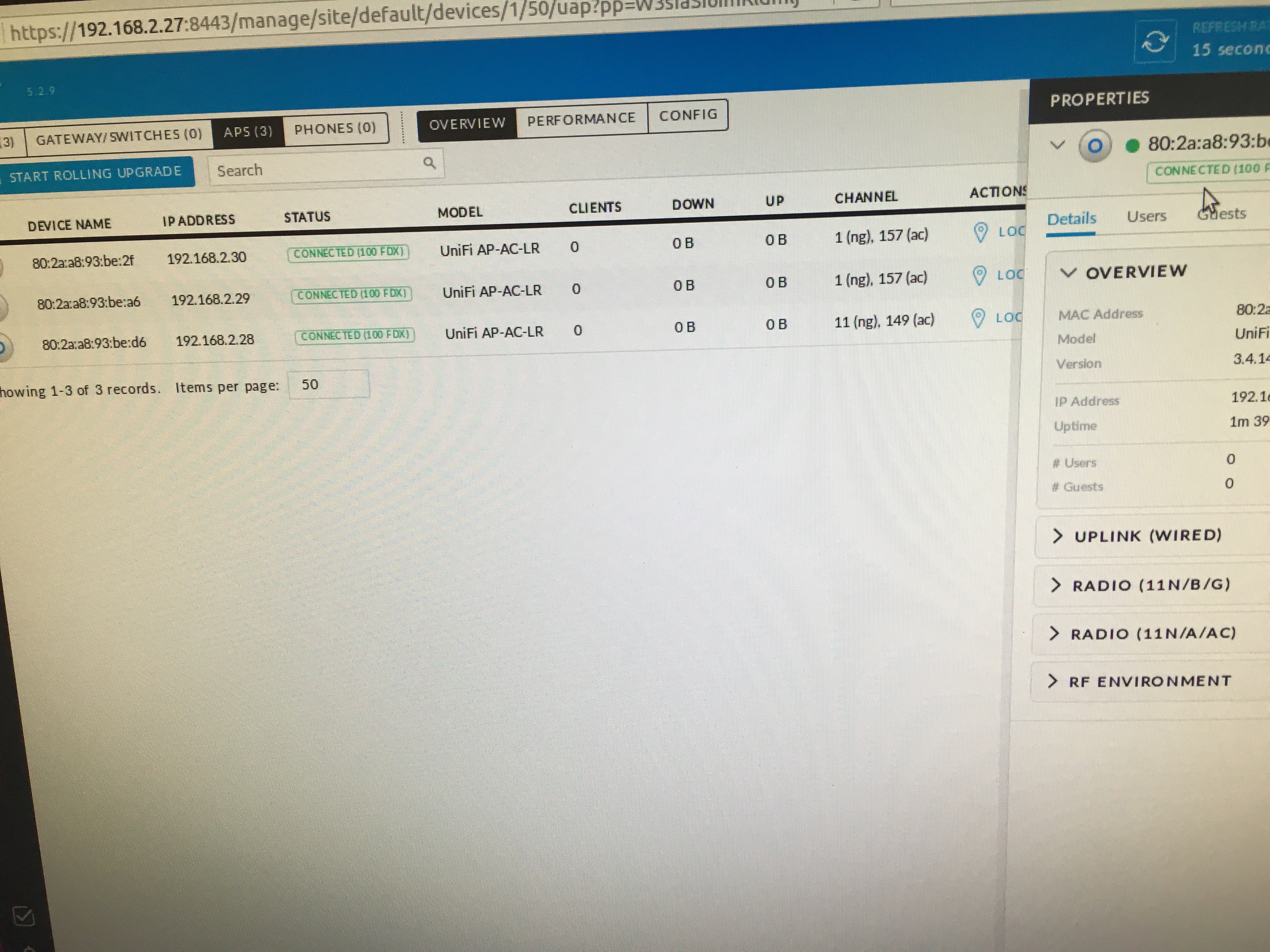
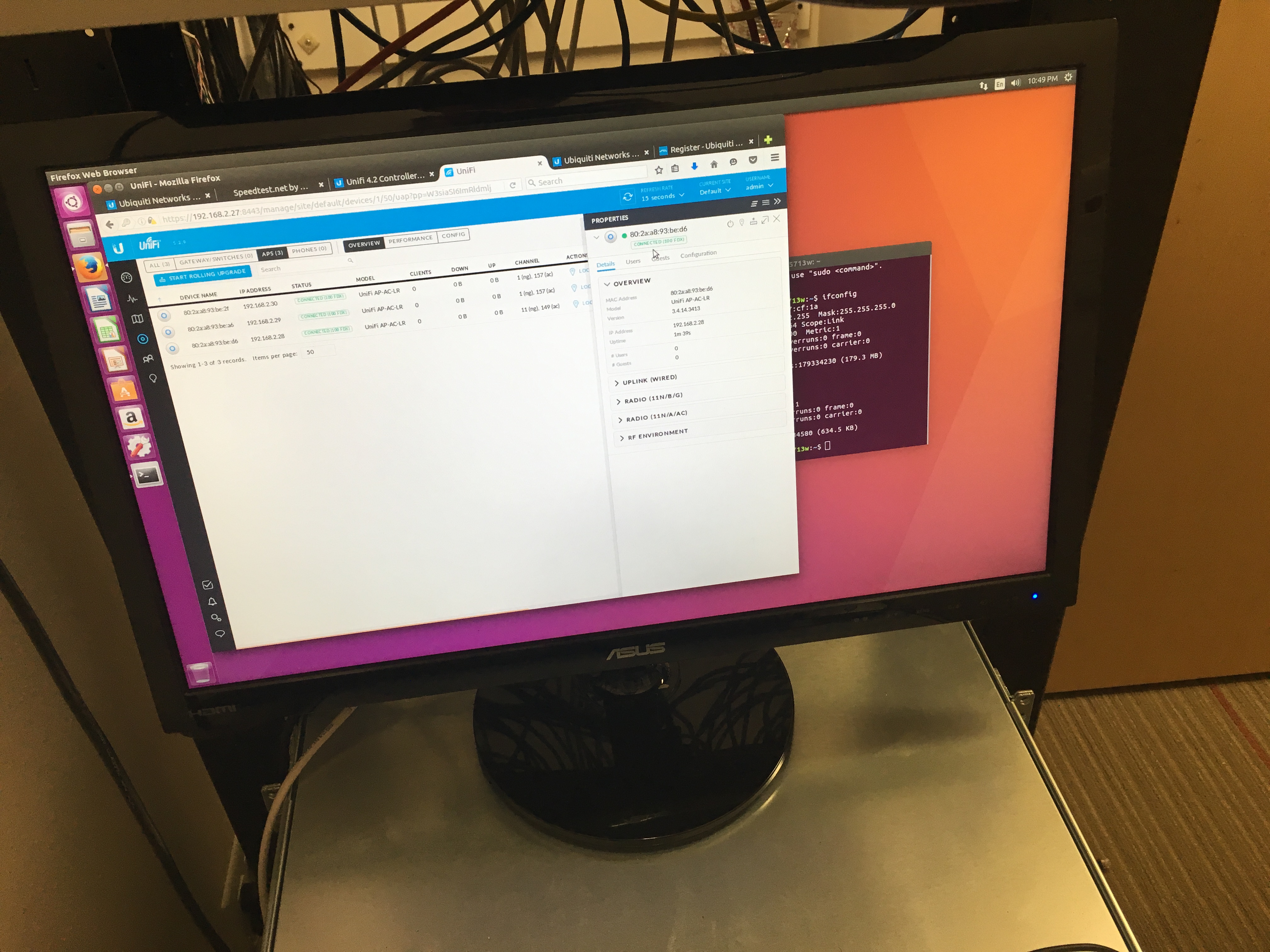
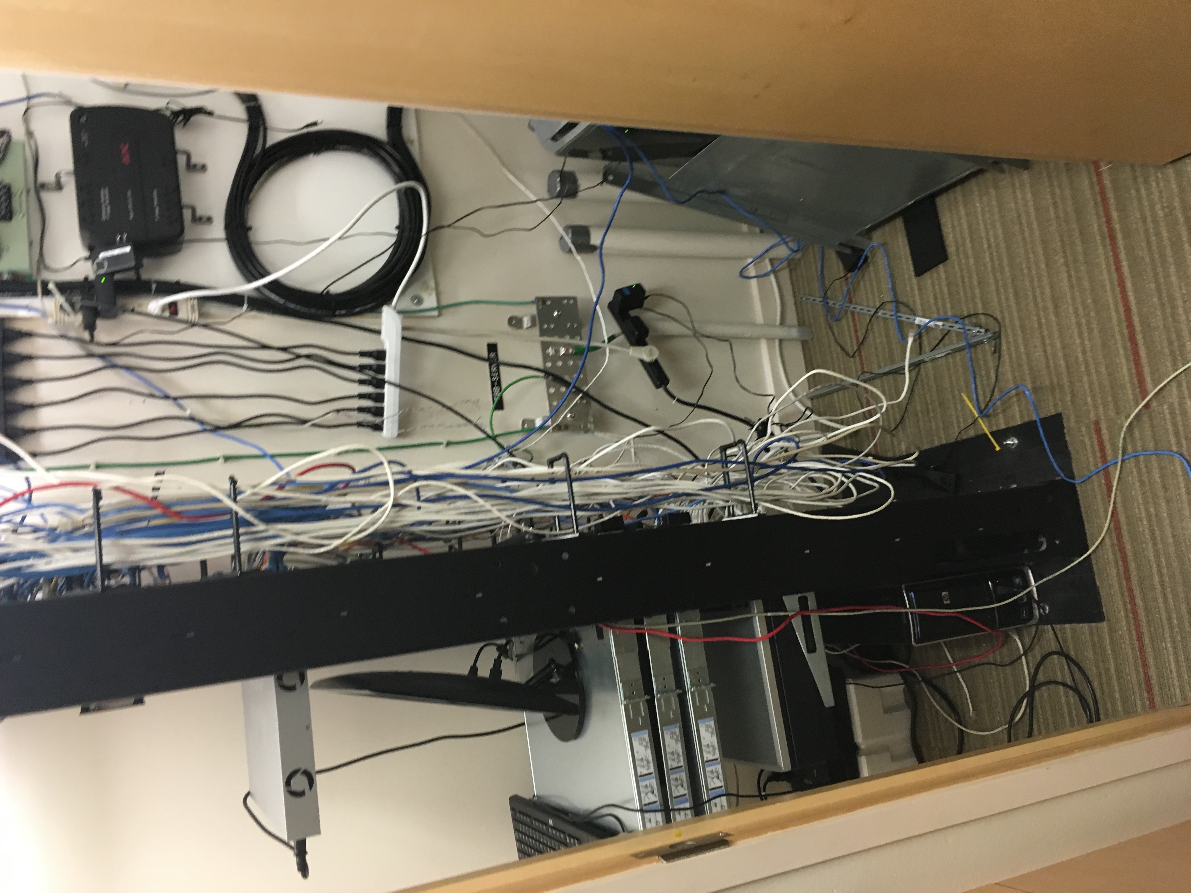
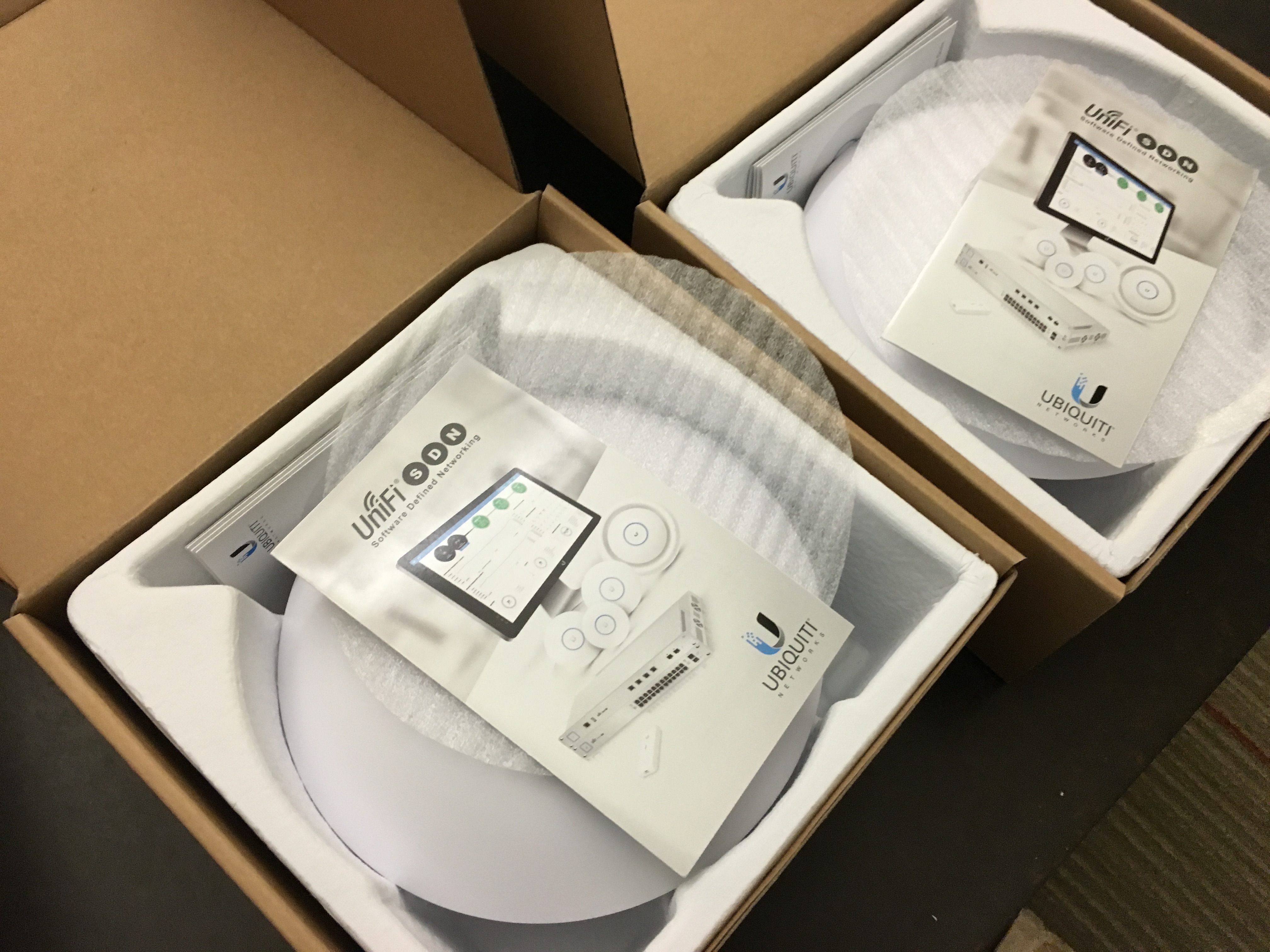
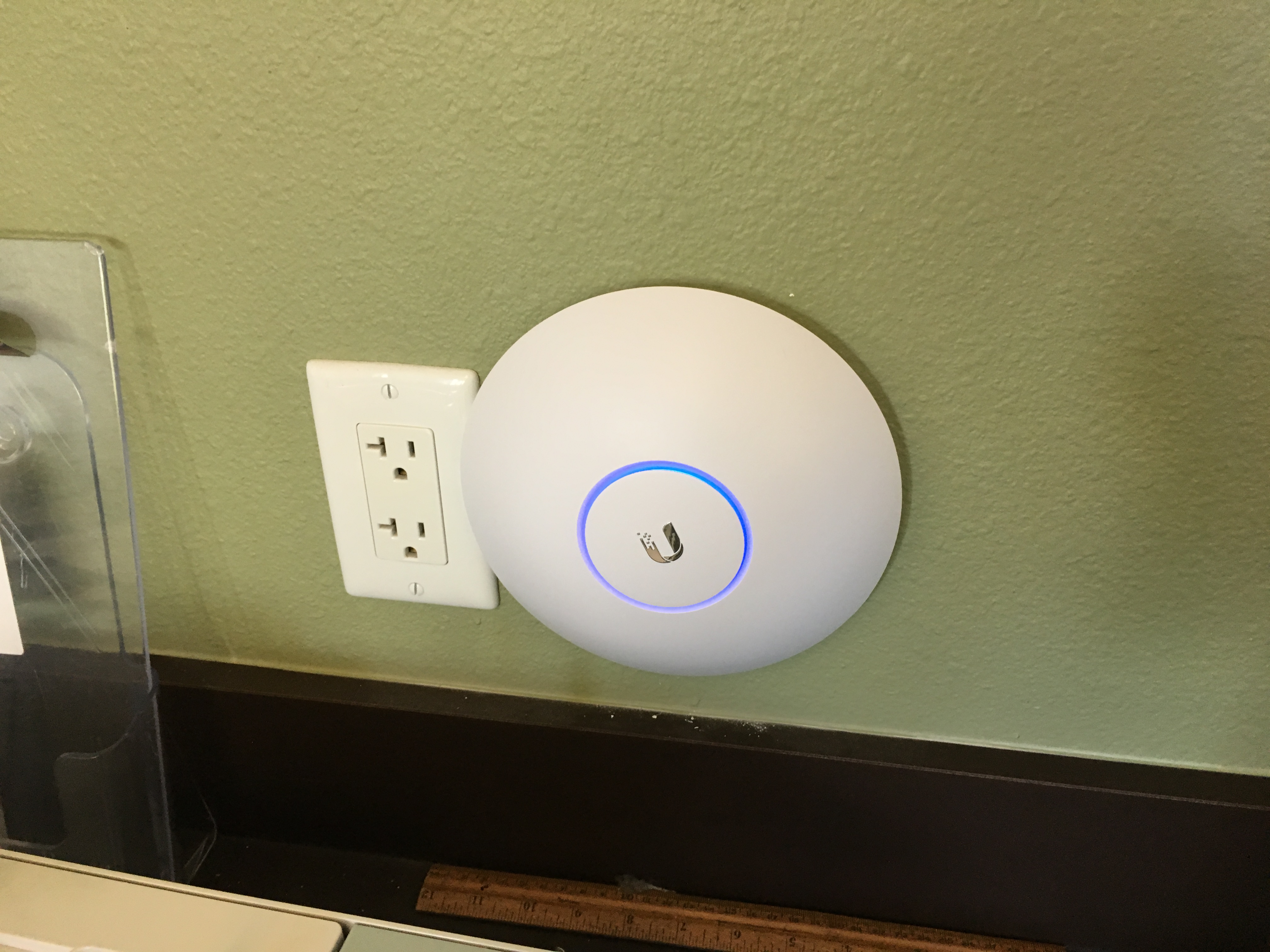
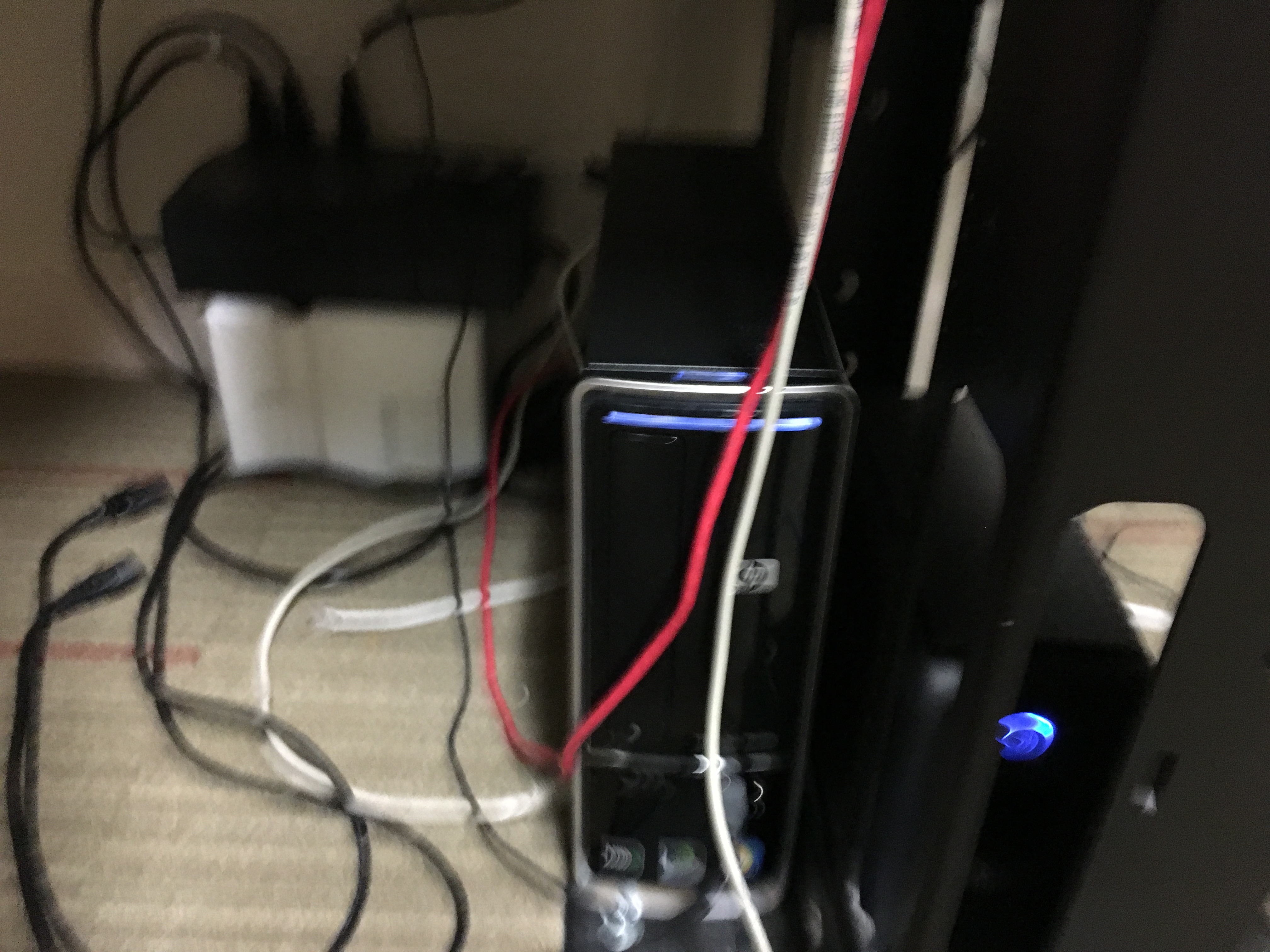
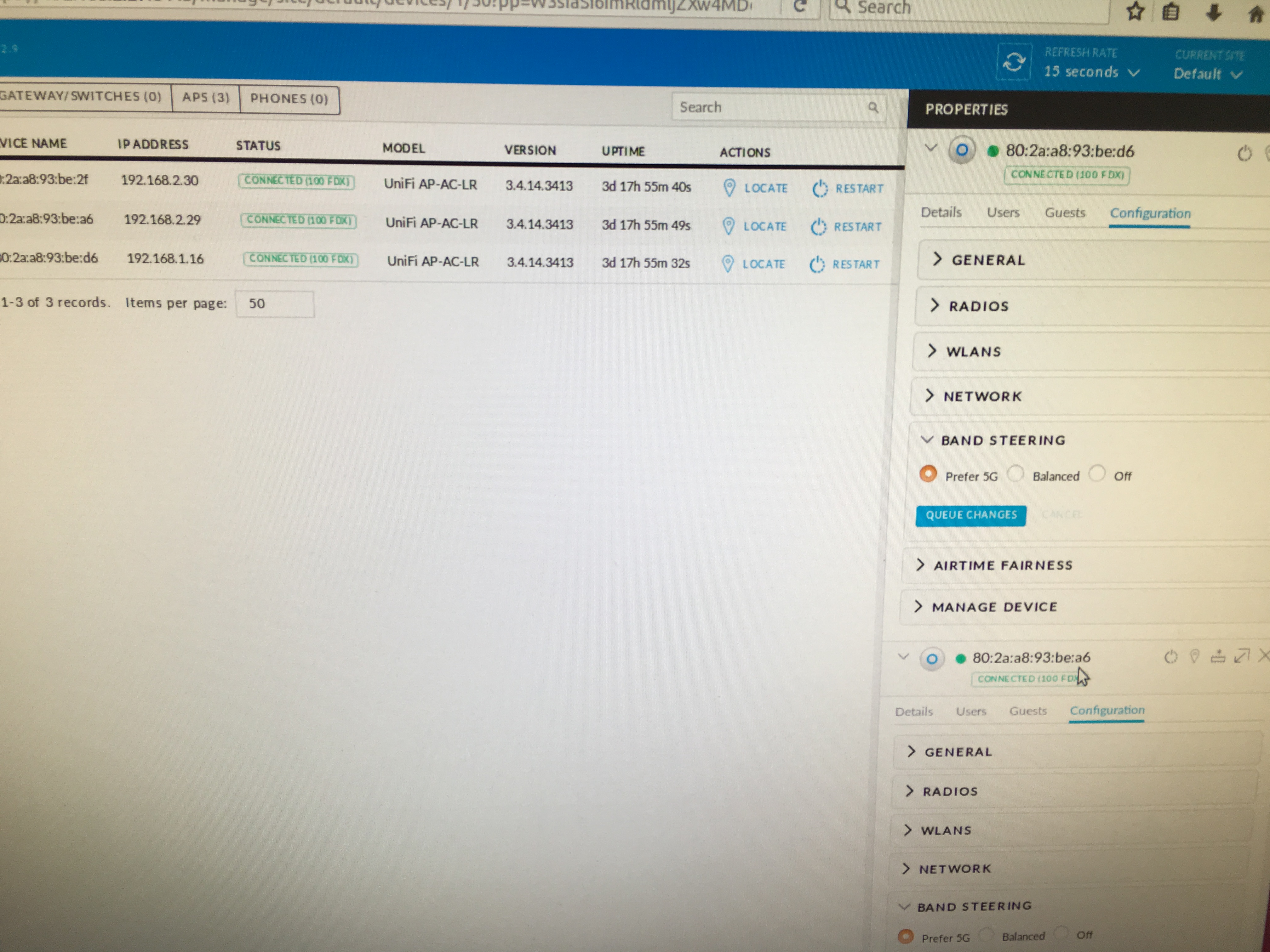
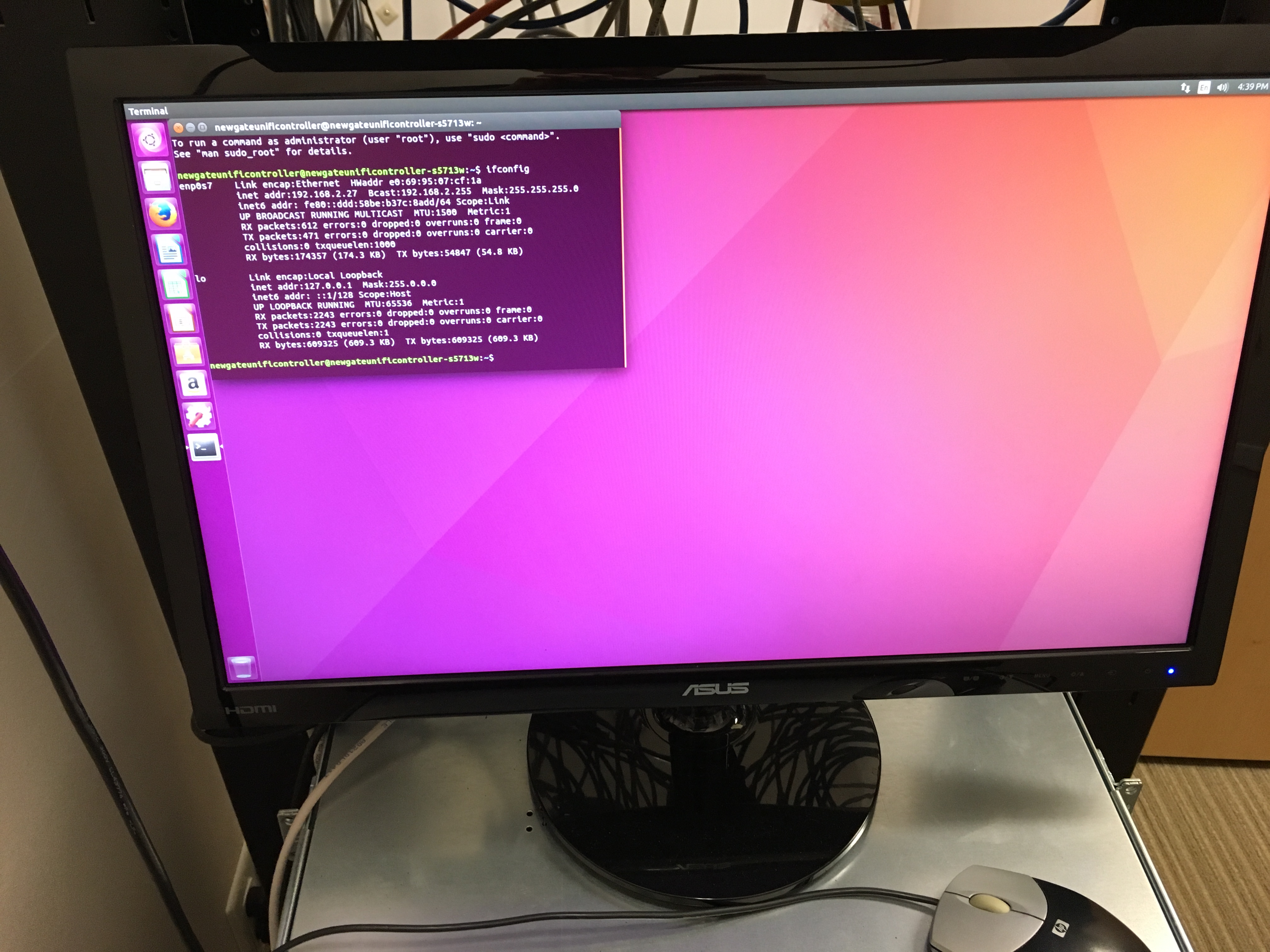
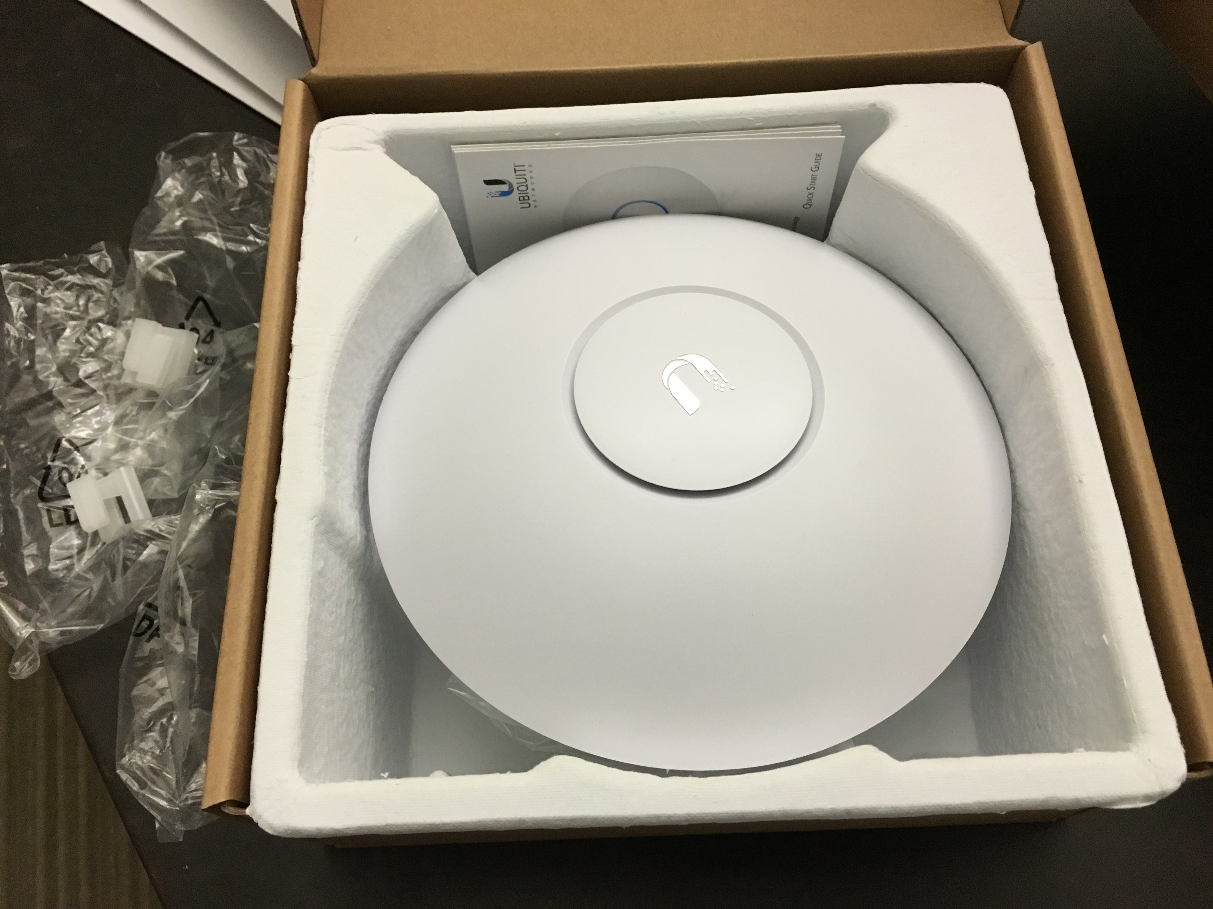
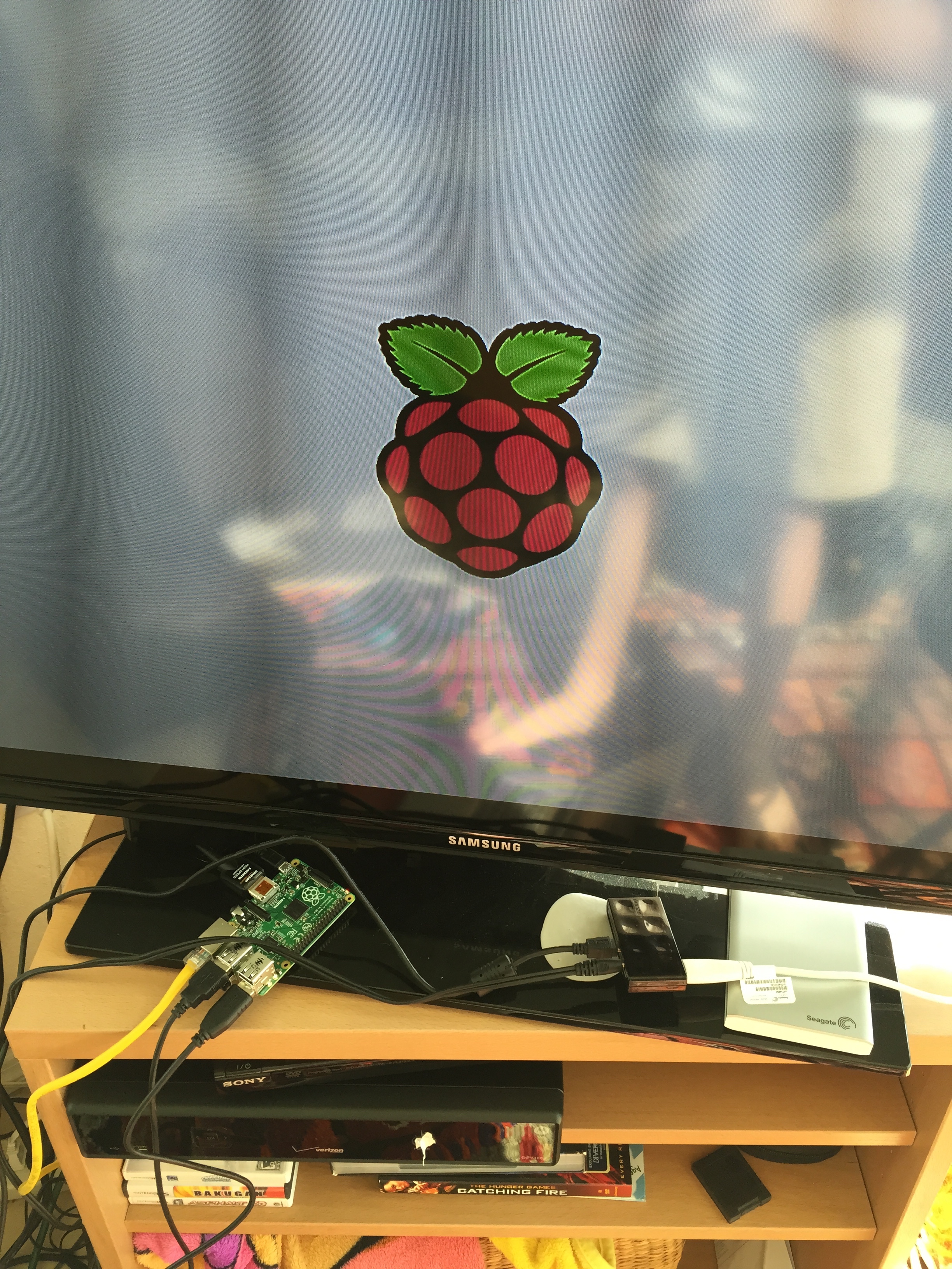
I was called in to make the internet work. I donated hours of time over the span of 5+ weeks investigation the system in place, organizing technology, setting up wireless access, creating servers, installing WiFi access points, advising, and troubleshooting. What I ended up creating was a network that consisted of a router/gateway, control server (running Ubuntu and Unifi software) and a set of 6 WiFi access points. One of the most difficult aspects of this project was first making sense of the already “established” network. The IT room that they had was a giant mess of ethernet cables, unnecessary hardware and locked servers that first had to be assessed and dealt with before any work even began.
One one day I even stayed on campus working on the system until 11pm.
This was helpful to my school as it saved them tons of money and I learned a ton throughout the process and had fun providing a service to my school that gives so much to me.
Below are some pictures of the process: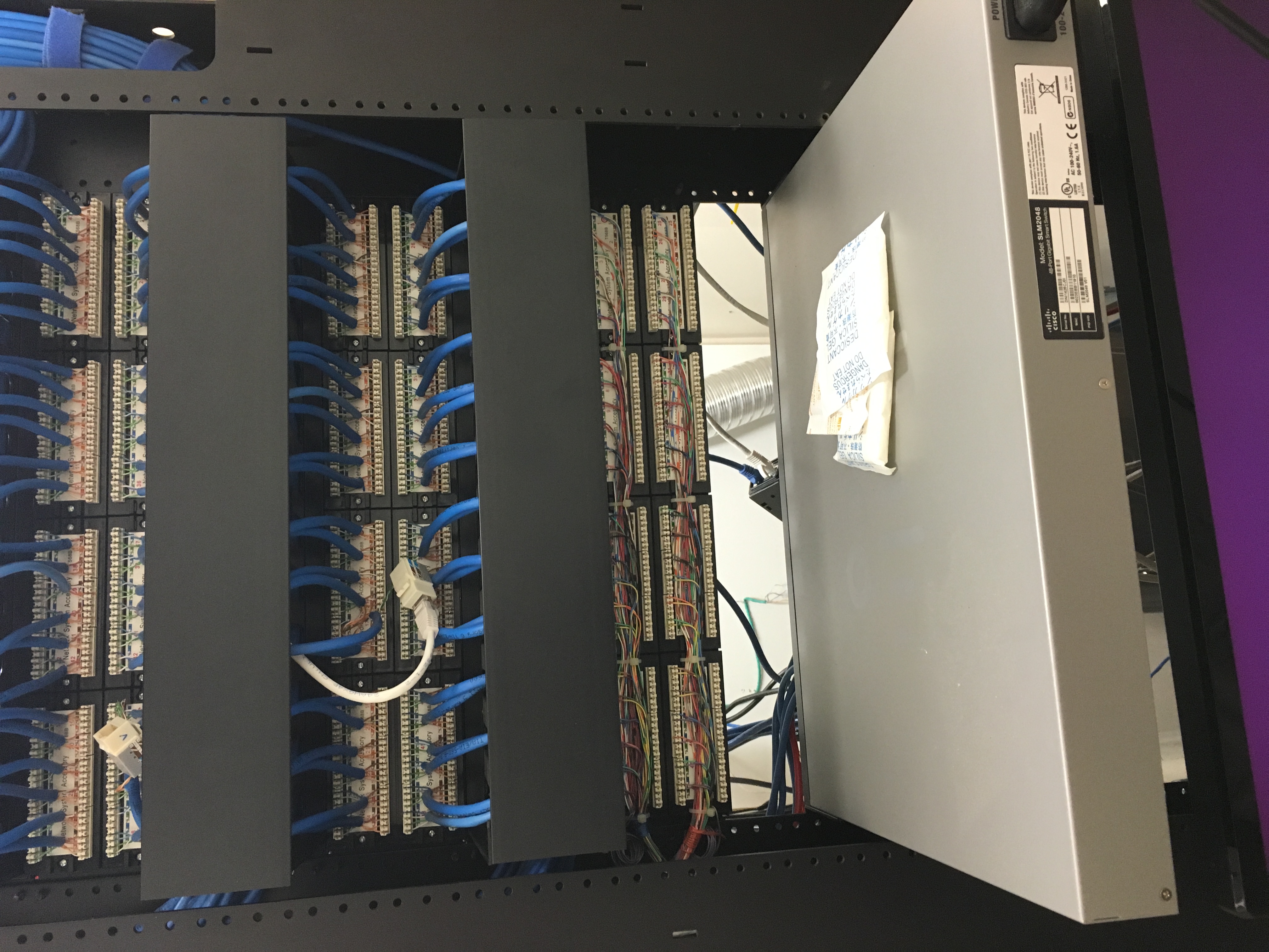

Raspberry Pi NAS
Recently I’ve been having some data management issues. I have an external 1TB HDD and an internal 256 GB SSD in my laptop and my mom has a multitude of external HDD’s (3-5) and we have tons of flash drives and ugg… It’s as if a bomb went off inside our data and scattered across 13+ storage media. To solve this issue we need a NAS. NAS stands for network attached storage and it’s basically an drive connected to the internet that can be accessed wirelessly or remotely by clients. I followed a YouTube tutorial by Tinkernut to install all of the dependencies for this NAS such as NTFS 3G and Samba. I got everything hooked up and connected and guess what? It worked! It worked, but not very well. I was only seeing speeds of up to 2 or 3 MB/s something was the limiting factor. It could have been the software, could have been the network (though unlikely, we have 75/75 internet) it could have been the USB 2.0 port or the lack of processing power on the part of the Pi. If I had to take a gander I would say that it was mainly the 700 Mhz Pi Processor in conjunction w/ the whopping 256 MB of RAM that did me in. Even i I did get it to work, I still want to add many more drives and connect them in RAID. I am currently planning a real NAS build w/ 16GB + RAM and a decent processor. To that I’m going to add 4 or 6 3TB HDD’s in RAID. Even though the Pi NAS was a failure in my book, it was a good learning experience and I had fun tinkering around w/ it. This project will have to be put on the shelf until the $$$ rolls in to build a good, useable NAS.
-Ben
Tennisball Air Cannon
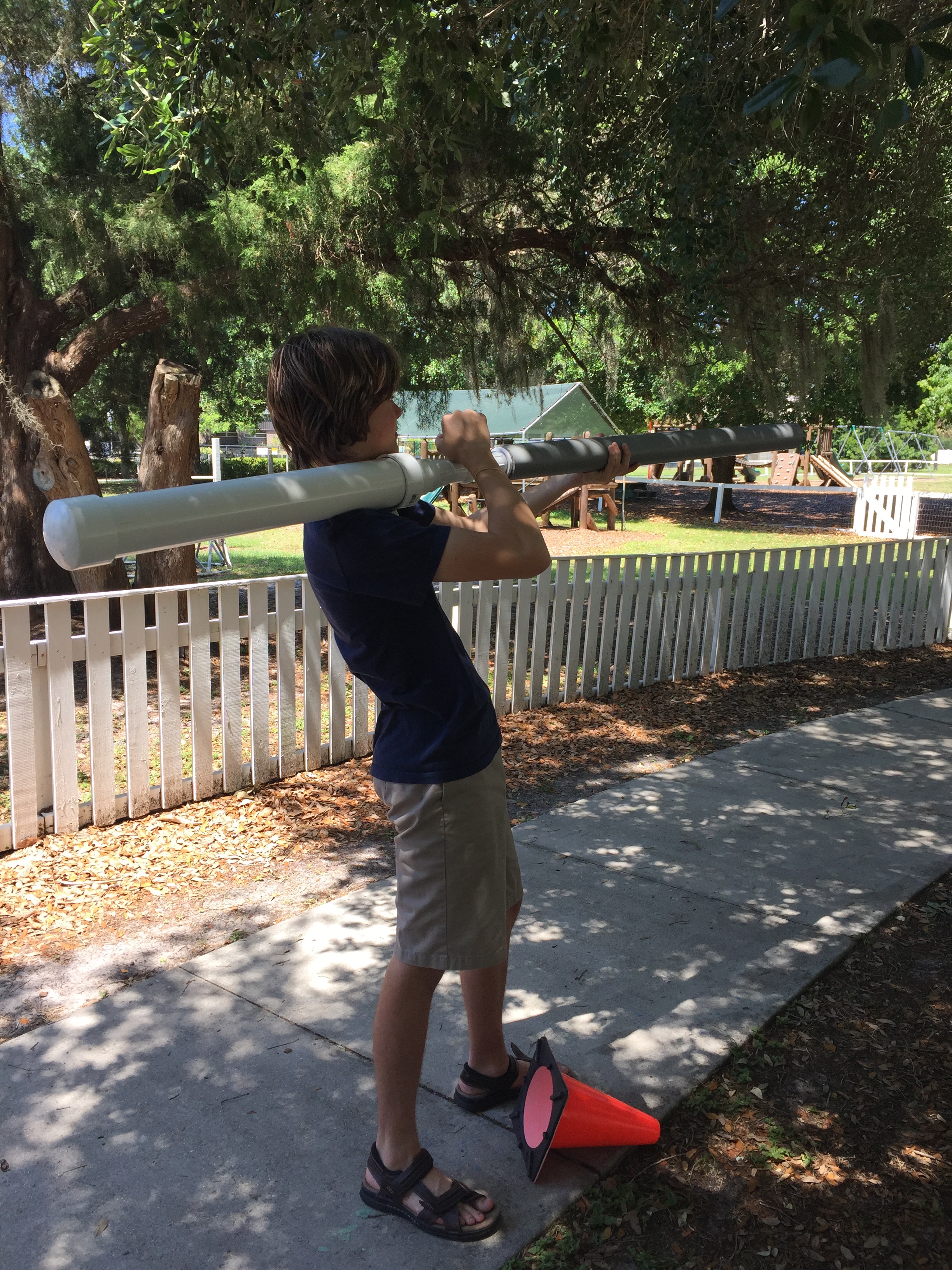
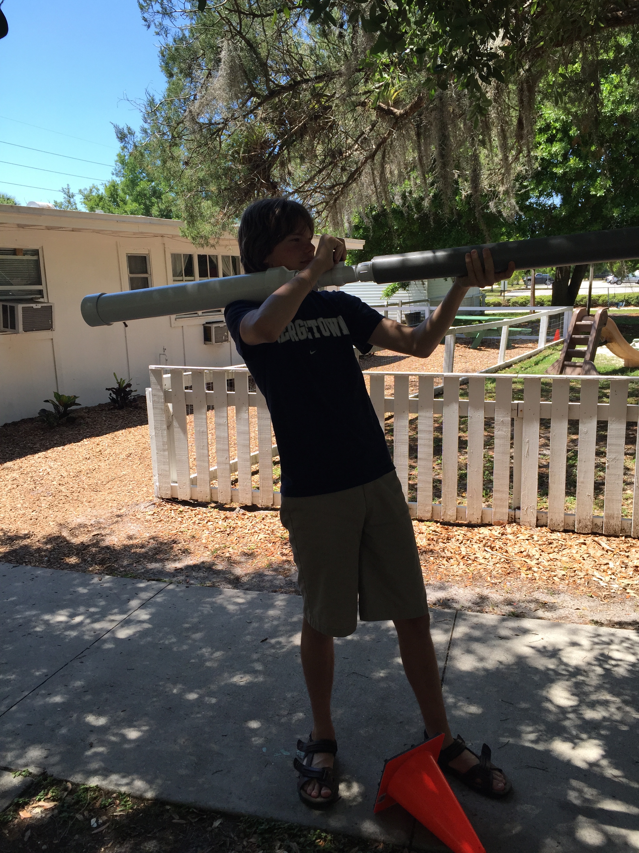
Hey there! At the end of the 2014-15 school year, right before summer break I finished my physics project. I took applied physics. One of the focuses of applied physics are hands on activities and experimentation. This project was designed to test the effects of different weighted projectiles. The air tank portion of the air cannon was built from schedule 40 PVC and the barrel was made from grey electrical conduit. The conduit had the perfect interior diameter for a standard tennis ball. For each test, the cannon was pressurized to 90 psi, set at a 45 degree angle, loaded, and fired. The only thing that changed was the weight of the projectile. The tennis ball was slit open and lead fishing weights were stuffed into it. I expected the graph of the distance to look like a bell curve with the lightest and the heaviest projectiles going the shortest distance. My results were totally different than what I expected. During my experiment I concluded that for this air cannon, the heavier the tennis ball the farther it would fly. This was quite contrary to the math that stated that the heavier the ball the slower it would go. I think though that if I would have been able to keep increasing the weight of the projectile it would have eventually slowed down. We have a very long driveway on the side of our school, the driveway is about 200m long. The cannon, loaded with a projectile weighing about 500g and pressurized was fired about halfway down the driveway, and it went so far then the projectile was lost in the woods. The tests ended there due to the fact that were were out of fishing weights. I estimate that tennis ball traveled at least 100m. 500g traveling ~40m/s comes out to 400 joules of energy, impressive! I really loved building and testing this cannon, and it was great to be able to do it as a school project. One thing that I learned from this is that theory and practice really can differ quite a bit.
-Ben
Pictures below:

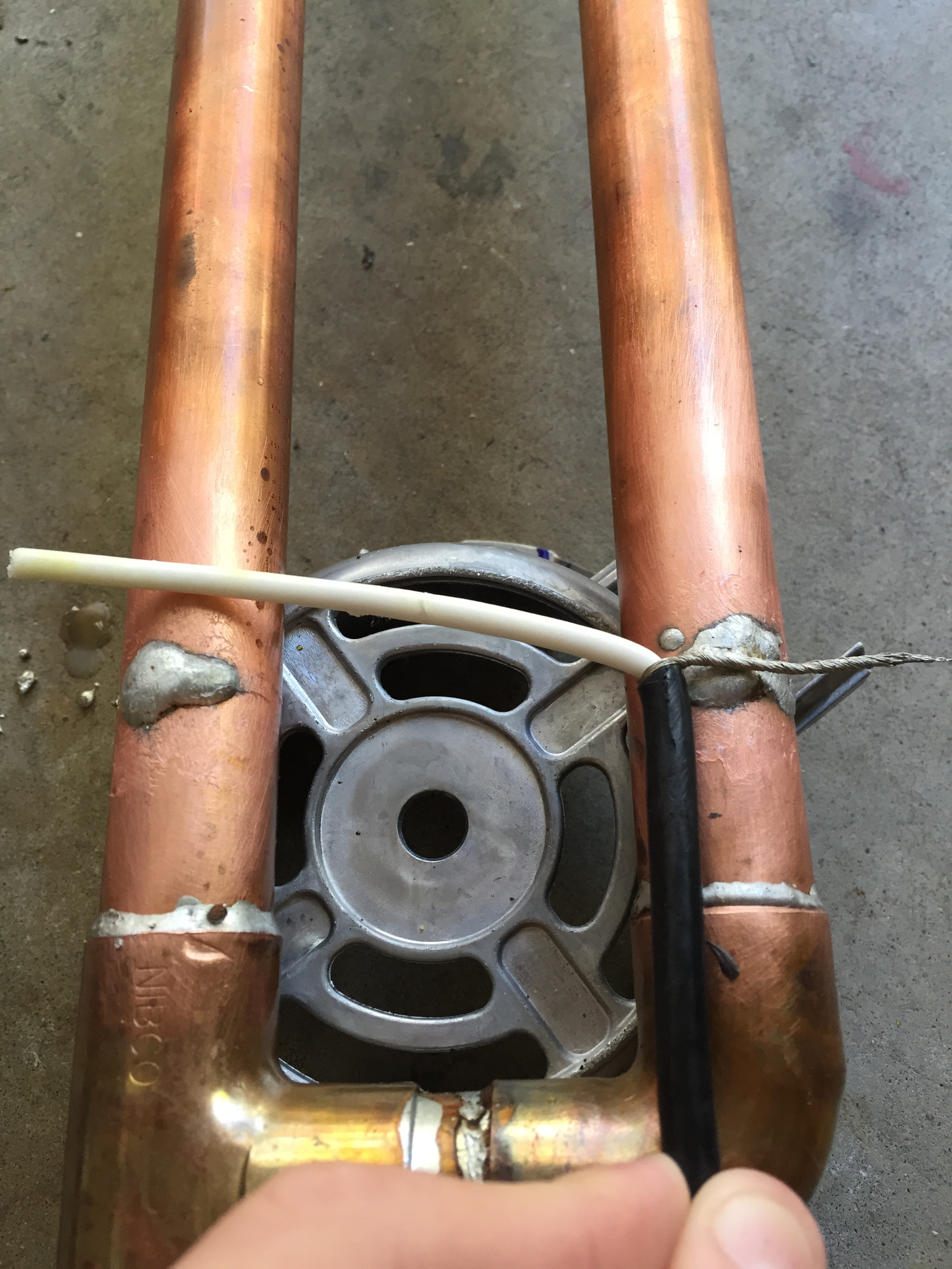
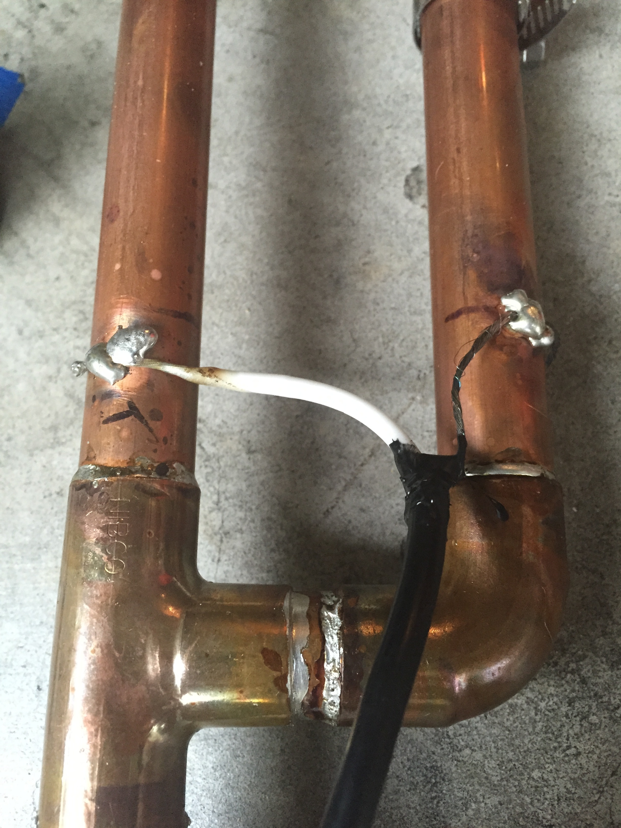
J-Pole Antenna
As you might know, I am an Amateur radio enthusiast. (KM4GPL) I got my license in December of 2014, so about five moths ago. I am currently studying to get my general class license. One of the things that I needed was an antenna for home.
As usual, the pictures of my build are below:
-Ben

Homemade 2×4 Desk
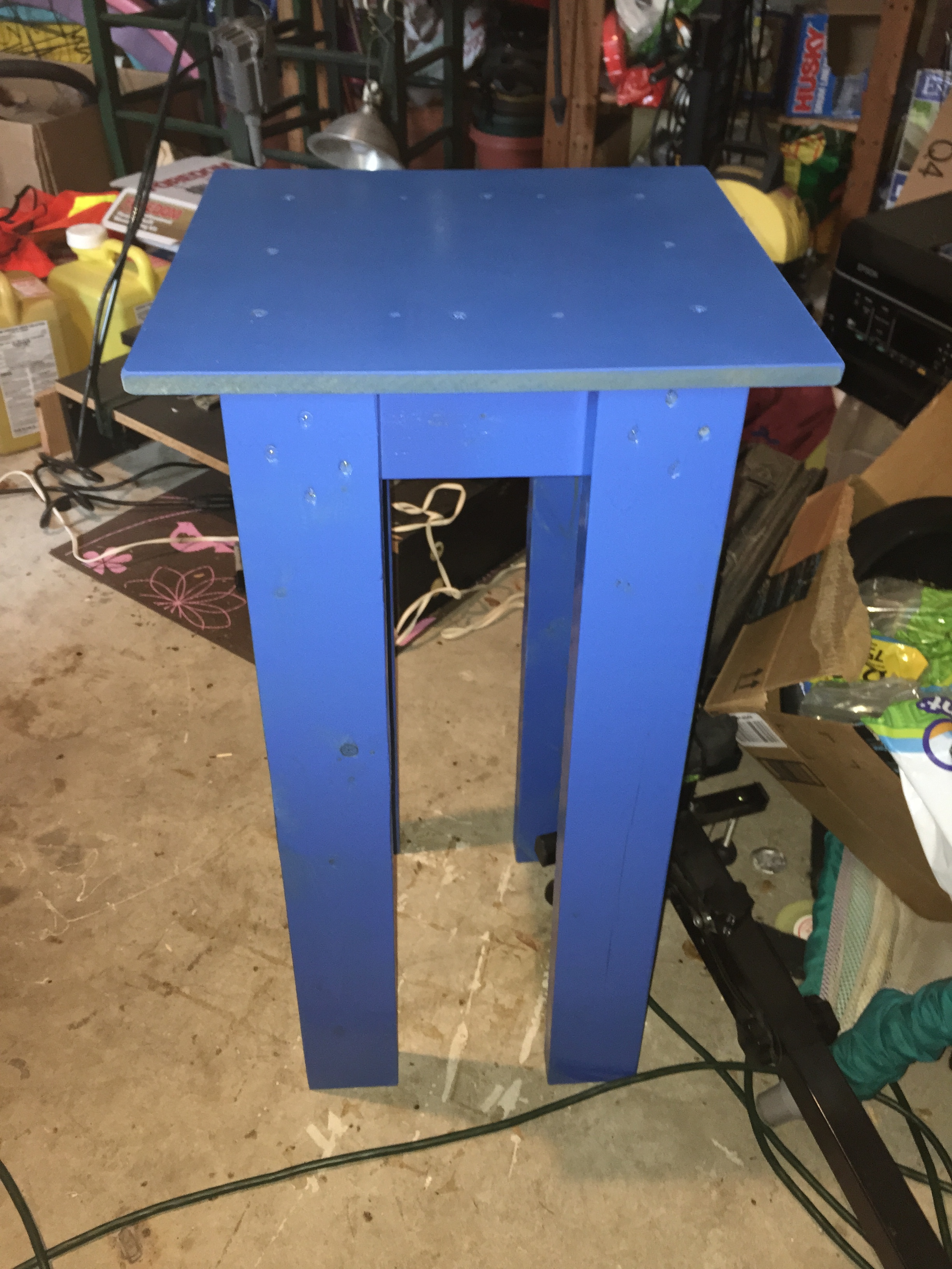
In my HAM Radio Update Update 1 post, I mentioned that I had converted a section of my room into a HAM radio shack. One of the first things that you need in a HAM shack is a worktable for doing your projects and storing your equipment. I had a very specific corner of my room in mind for my ham desk and after a trip to IKEA, I determined that there were no desks there that fit the space I needed. Most were way too big and some were too short. Instead, I decided on building my own desk. I would build the frame out of 2×4’s and the top would be MDF (Medium Density Fiberboard). After a quick run to the hardware store for the 2×4’s and some more long screws and paint, I was done gathering the materials. I assembled the frame and attached the MDF to act as the table portion. One of the main reasons that I chose to build the desk myself was because the space I wanted to fill was an irregular polygon (looked like a rectangle w/ a little square sticking off of it on the upper right side). Anyway, my idea was to build the table in two sections: one large rectangle and one small square. I would then join the rectangle to the square once the desk was in place. After building both sections of the desk, I sprayed them with multiple coats of blue spray paint. Unfortunately, the newspaper that I placed down to protect the surroundings from my beautiful shade of blue wasn’t big enough… oops.. sorry driveway :/ After I was done spraying the tables blue, I hit them with two coats of clear lacquer. After it was all dry, I screwed both pieces together and pushed them in place! Done! For about $25 in materials I made tables that would have cost about $200 – $250 in a retail store. I was pretty impressed with myself, albeit a bit upset that I had accidentally painted the driveway. Like I said before, if I could do anything over, I would pick a bit darker shade of blue for the tables, and not paint the driveway on accident.
As usual, the pictures are below:
-Ben

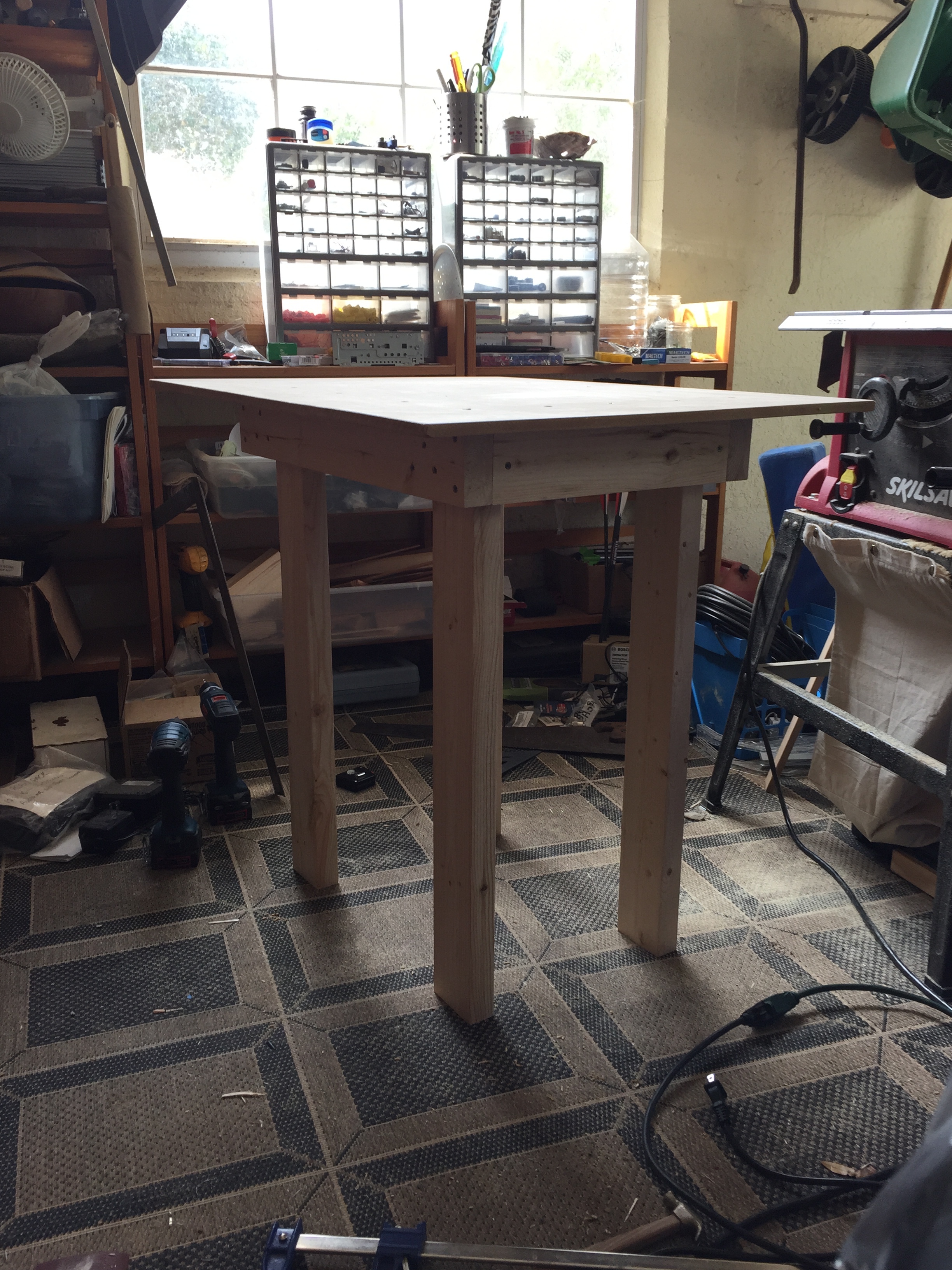

(Above is the desk in its final resting place. My ham equipment needs organization.)
Minecraft Wooden Chest
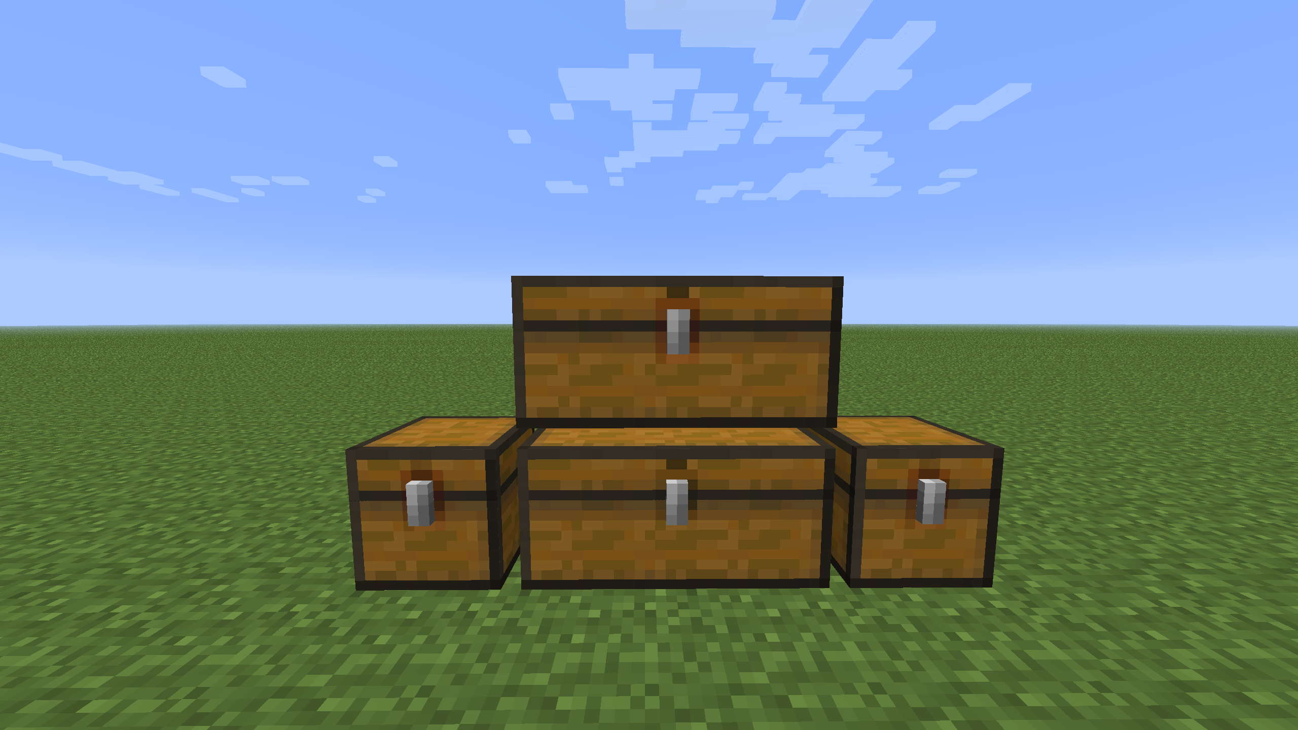
Minecraft! Who doesn’t love Minecraft? In case you haven’t heard of Minecraft (Hereinafter to be known as MC), MC is a single & multiplayer sandbox block based game. Your object is to survive and to build, construct, mine, farm, dig, fish or do just about anything else. In MC the primary place you store your items are in chests. Other people have created MC chests before, but they are either printouts that you print and then glue together or they are cheap Chinese pieces of plastic that don’t even look like real MC chests. The first picture below is a picture of chests in the actual Minecraft game and the second picture below is one of the printout and fold together chests that I mentioned earlier.

So with the background info out of the way, and also mentioning that MC is one of my favorite games, I set out to build my own MC chest. Out of real wood! This was a fairly recent project, done w/ my table saw, but before my electric sander :/ This project was completed around February of 2015.
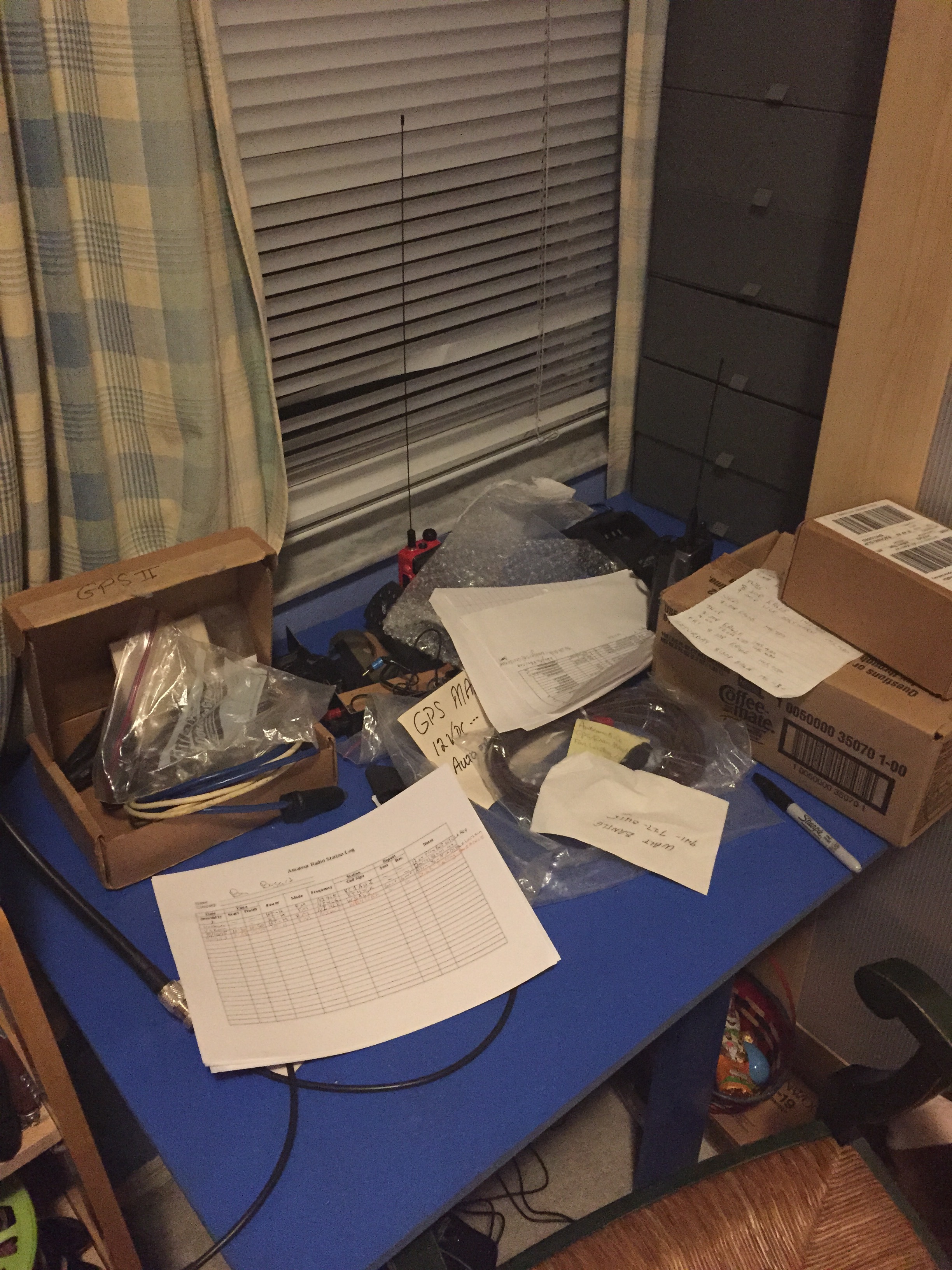
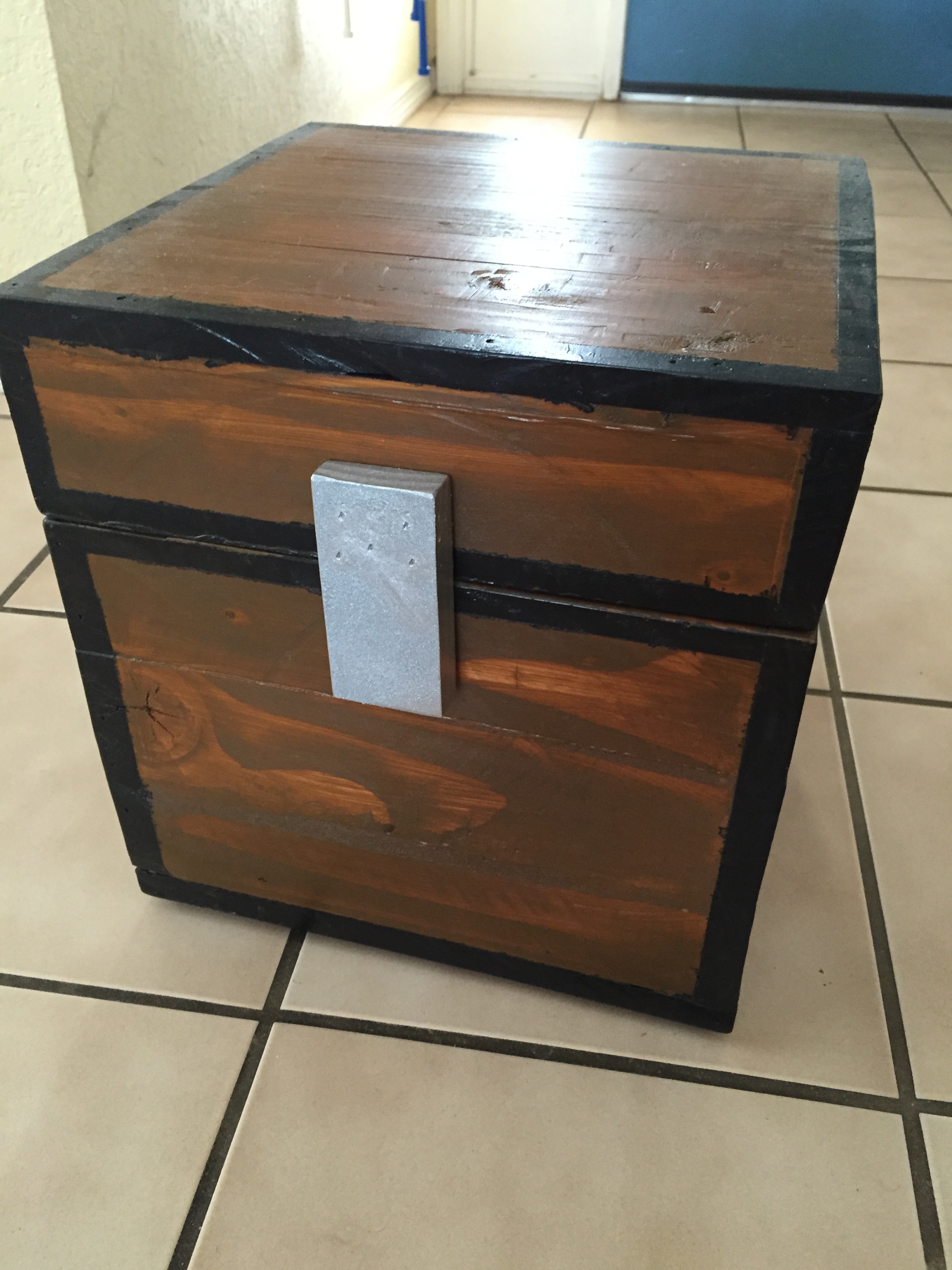
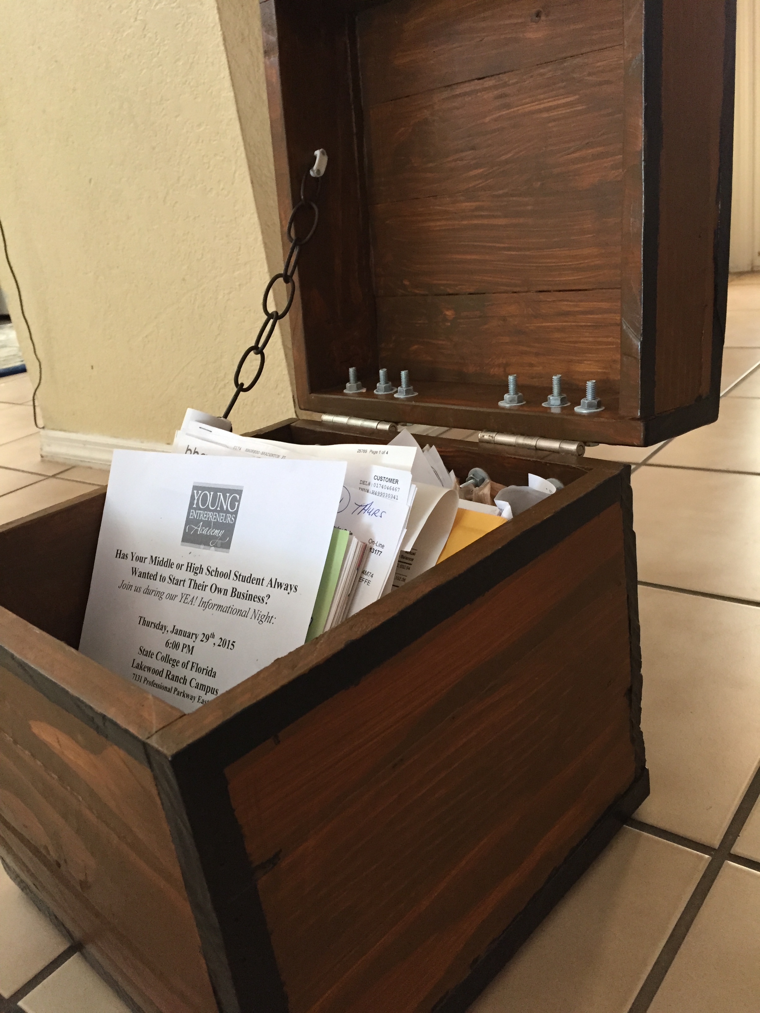
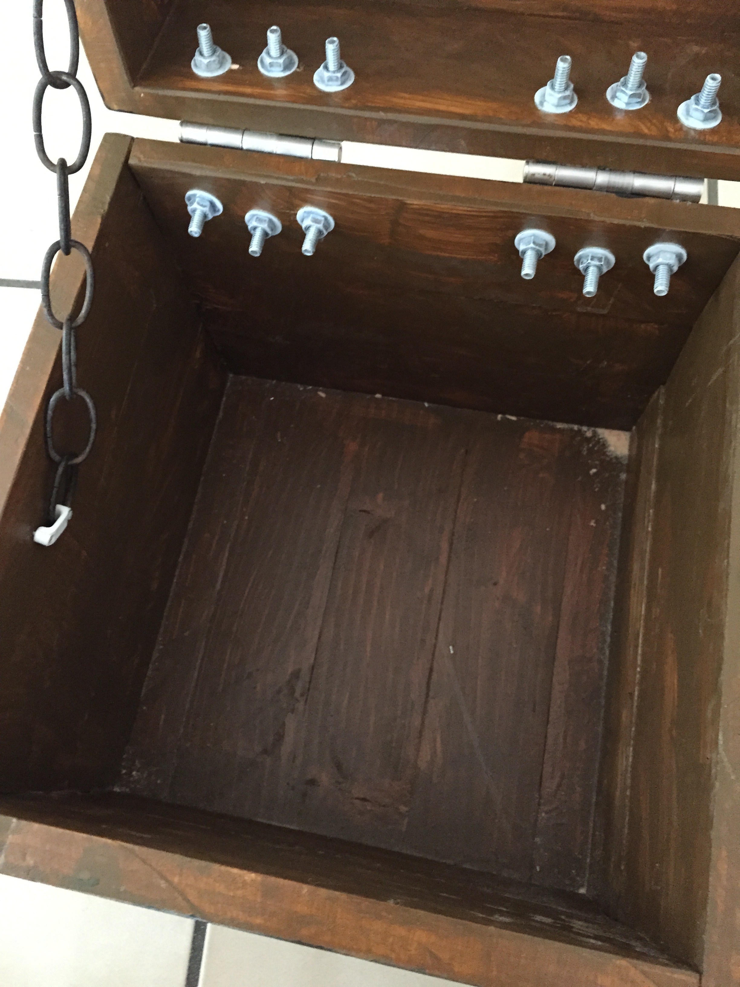
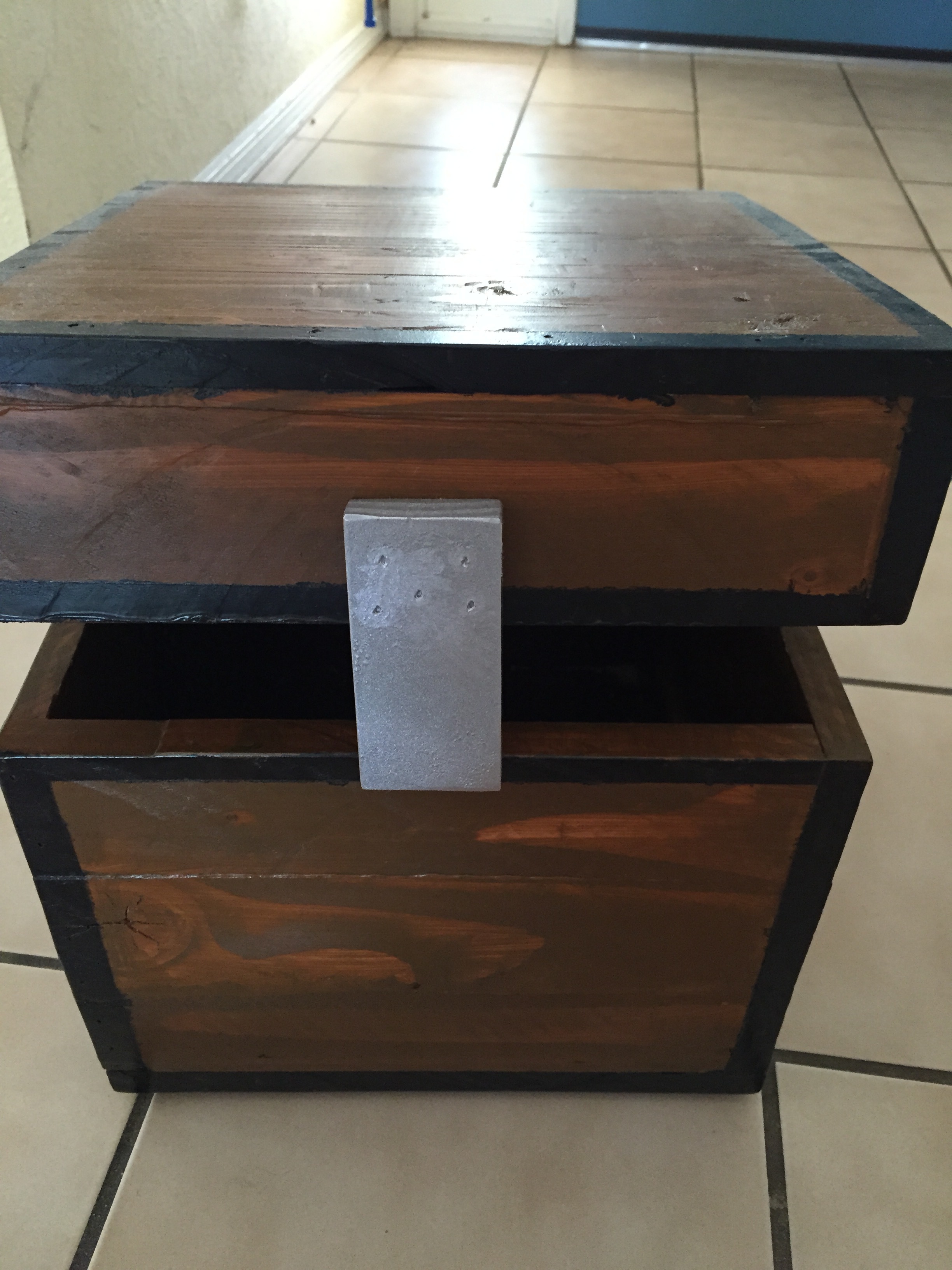
If you have read the rest of my posts you’ll know that I built a trebuchet before that launched HDD’s across the road. The treb was taking up too much room just sitting there, sooo… sacrifice.. sacrifice.. sacrifice. I dismantled the treb, cut out the bad parts, ripped the 2×4’s into boards that were approx. 3/4″ x 3 1/2″. I then glued the boards together into rough sheets, planed them down with a hand plane, cut them to the right dimensions and glued and brad nailed them together. I then stained the entire thing and added the silver “lock” on the front. I added some feet to the bottom so it wouldn’t scratch and then it was almost done. I added some hinges and a chain to keep the lid from falling all the way open and now I can store anything from cash to papers to schoolwork in my homemade Minecraft chest made from recycled trebuchet wood!
As always below are the pictures from my build!
-Ben

Stocks
Hello! This was a project that a did two years ago (2012 or 13) for History Class. We were learning about early settlers of the US and we were supposed to do a project relating to the life of the early settlers. I asked my history teacher if I could build something and he agreed as long as it would pertain to the subject. So I built stocks which were used a punishment or humiliation in the town. So naturally, I put my mom in them  Below is a picture of her in the stocks and also a picture of me holding the top portion up. This was a fun project especially because I didn’t have very many tools at the time so it was a hand saw, a drill and a screwdriver for me. If I were to repeat this I would use a jigsaw to cut circular holes and sand everything smoothly. Either way, being able to lock anyone up was pretty fun!
As usual, below are the pictures:
-Ben
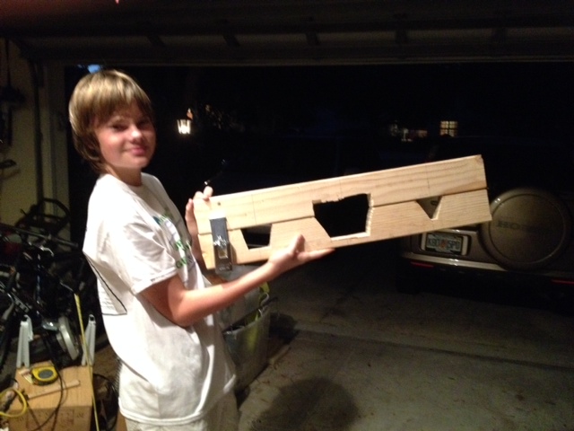
(Me holding the stocks up.)
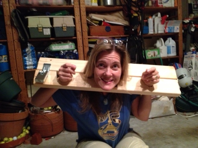
(Locked my mom up ;))
Reverse Geocache
Hello,
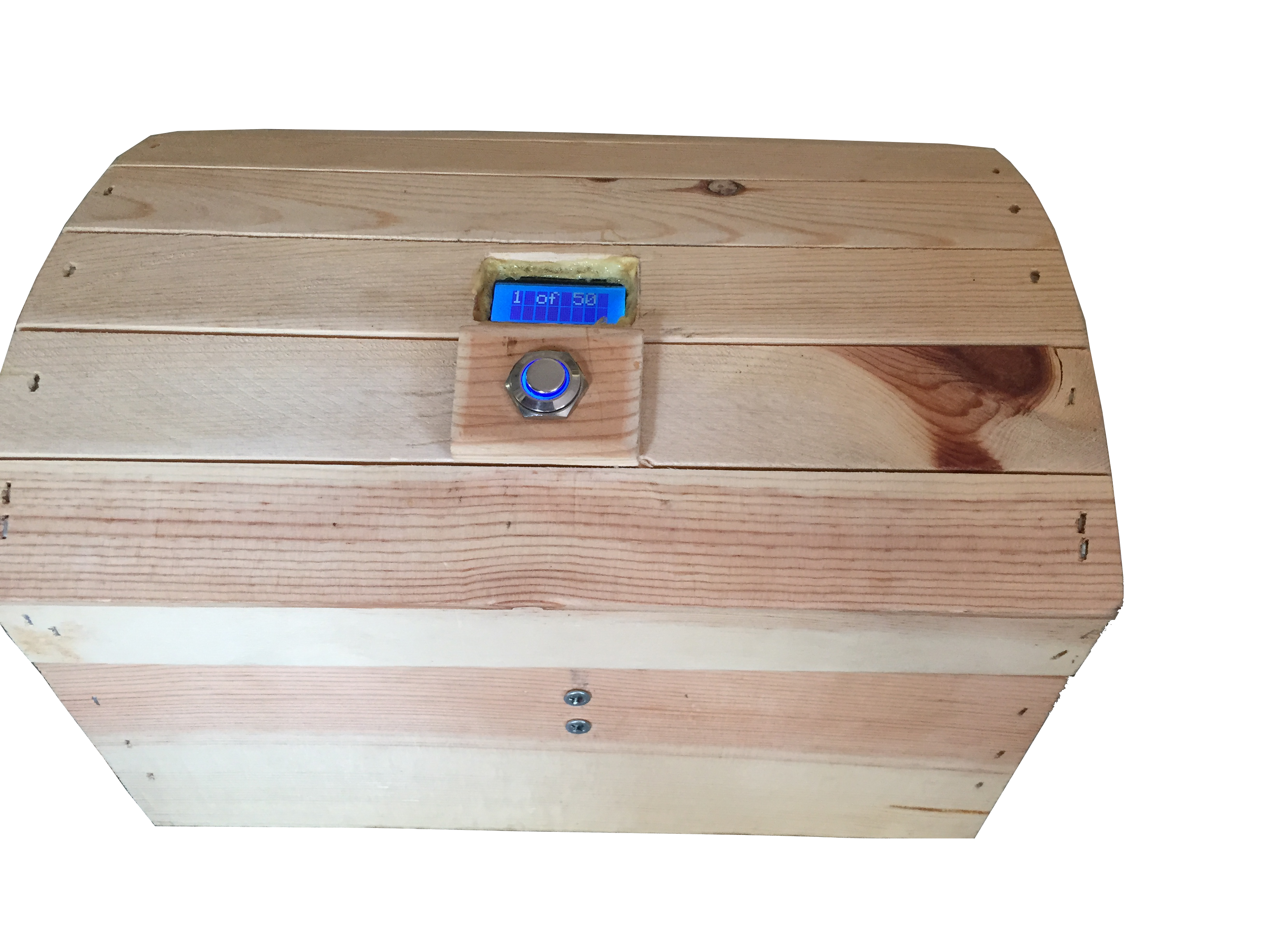
This post is part of my ongoing effort to update my website with my previous projects. This one was created in late 2013 as you can see from the pictures below. The above picture is a picture of my reverse geocache I made. The software aspect of this project was quite challenging as was the hardware aspect as well. First off, in order to explain what a reverse geocache is, it must be known what a normal geocache is. A geocache is a box or container ranging from pill bottle size up to five gallon bucket size, it is hidden and the coordinates of its location are posted online at geocaching.com. People then attempt to find it using their GPS and when found, they log their find online. This geocache works the opposite way in that the cache is always with you and the object of game is to bring it to a set of coordinates unknown to the holder. You simply press the button, the GPS then gathers your coordinates, parses the data and outputs you distance to the object. The most efficient way of solving the puzzle is to take three distance measurements and then to use triangulation to determine the final location. In the code (originally by someone else, I kept the GPS data parser and re-programmed the rest in C++ in Eclipse and then sent it to the Arduino) there is a user definable variable to change the valid final location radius. That allows you to set the final location as a park bench or even as an entire city. When the box reaches the final location, it displays “Access Granted” and rotates the servo, retracting a pin holding the box lid shut. There is a secret back door I added in case I needed to open up the box in a pinch, but thats secret and will remain in my brain. Overall this was a challenging project and if I could change something, I would stain the wood a dark brown (I still could…) and I would use a sturdier locking mechanism.
As usual, pictures with explanations are below. Live long and prosper. (Leonard Nimoy, *sniff sniff*)
Ben
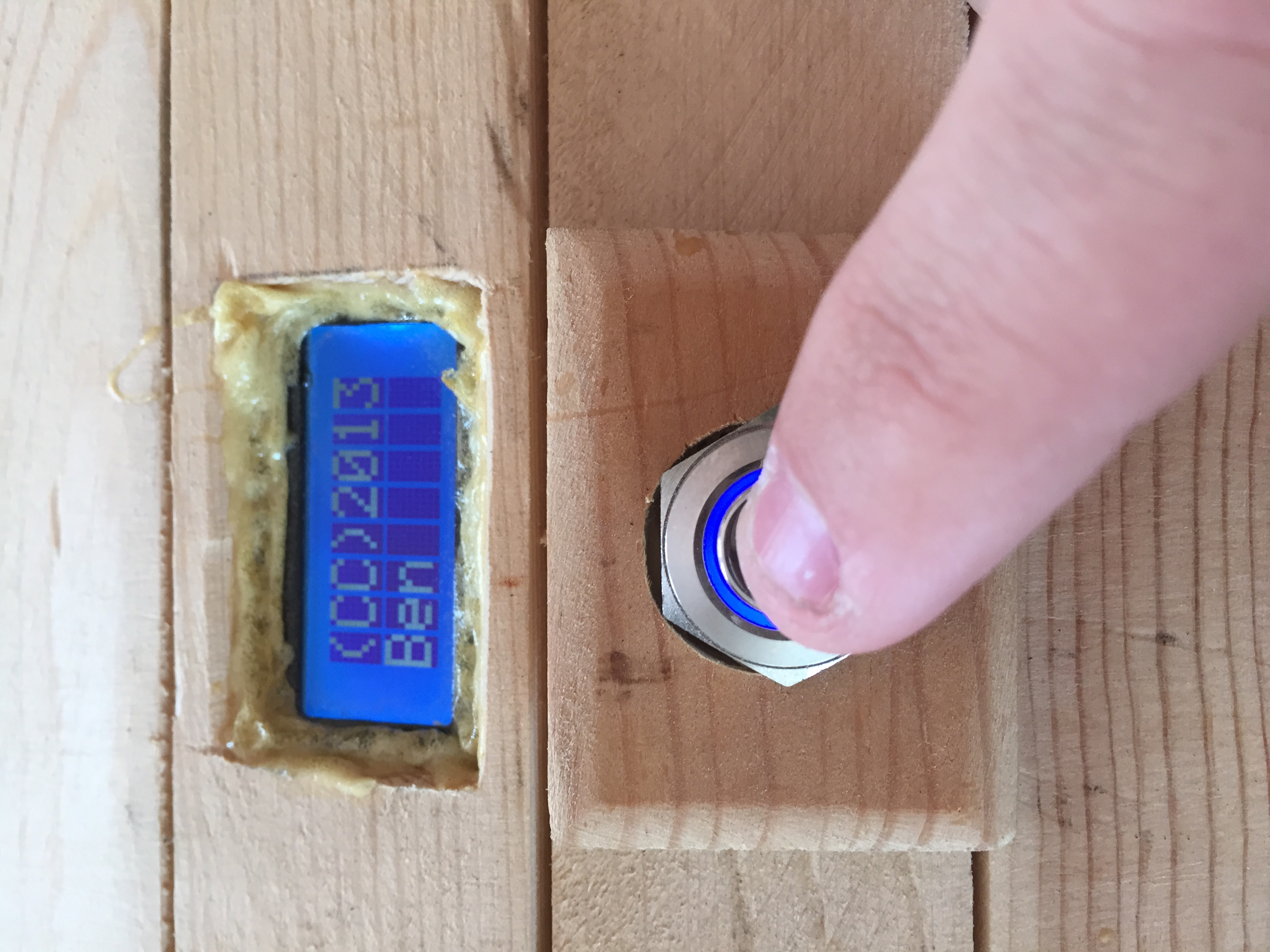
(The welcome message displayed when first hitting the power button.)
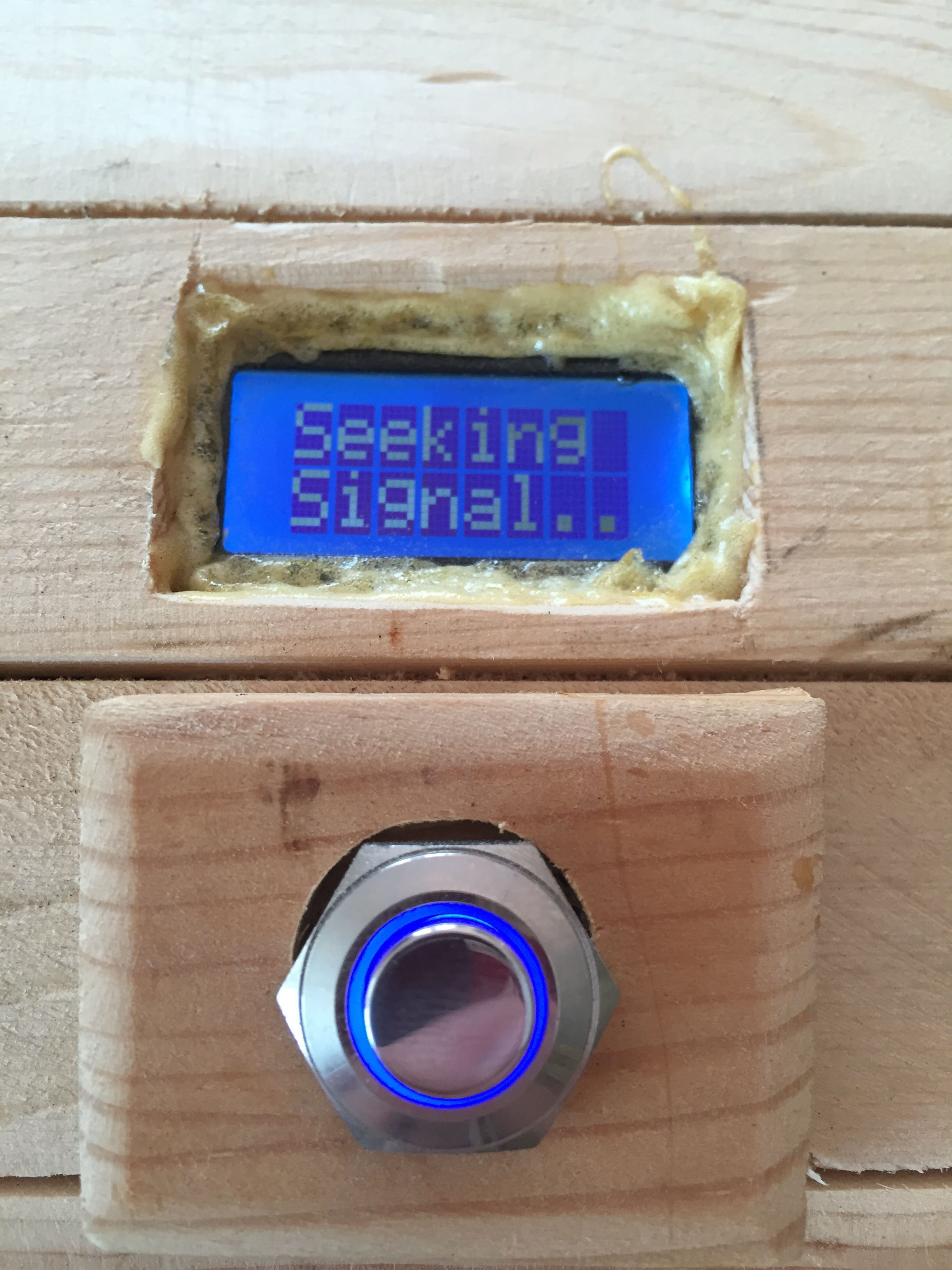
(After displaying the welcome message, the Arduino uses the GPS to look for a signal from the orbiting satellites.)
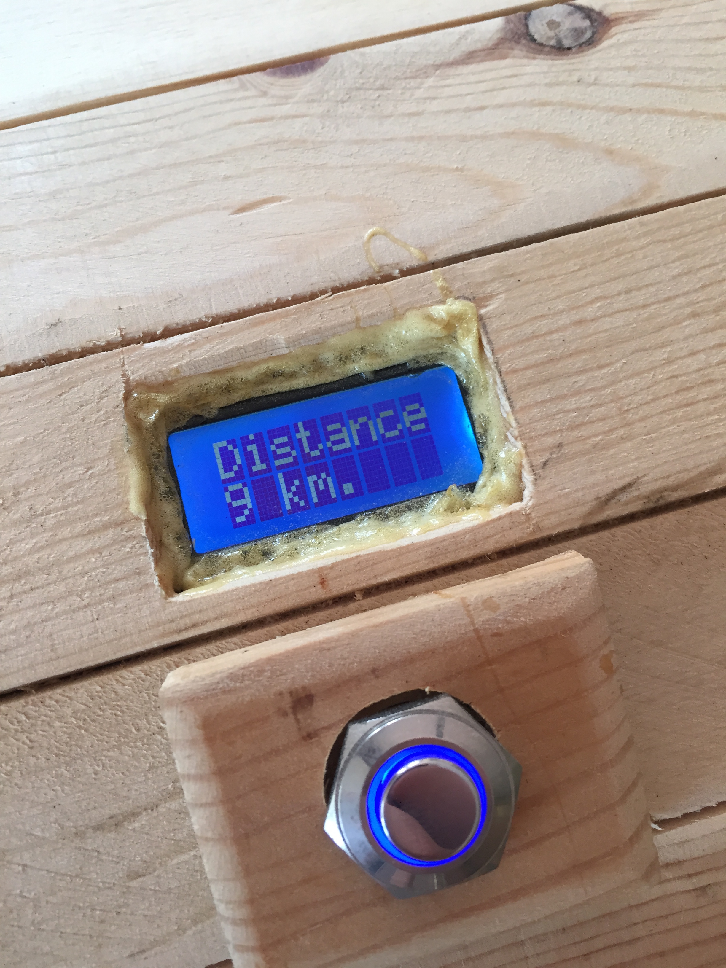
(After acquiring the signal and parsing the data, the Arduino displays the distance from the target. Here we are 9 km away from the target.)
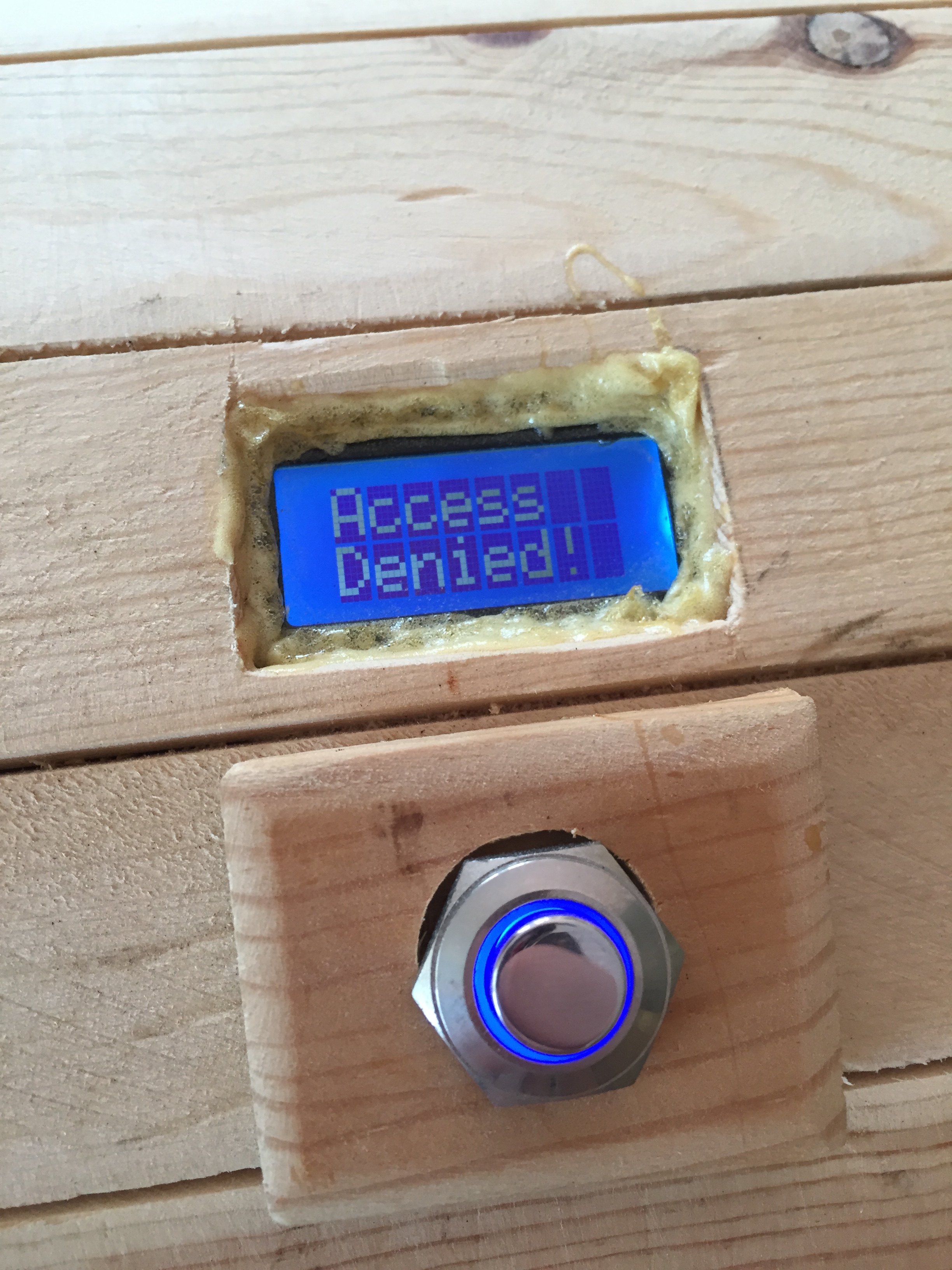
(Since we were 9 km away from the target, the Arduino prints “Access Denied” and doesn’t move the servo.)
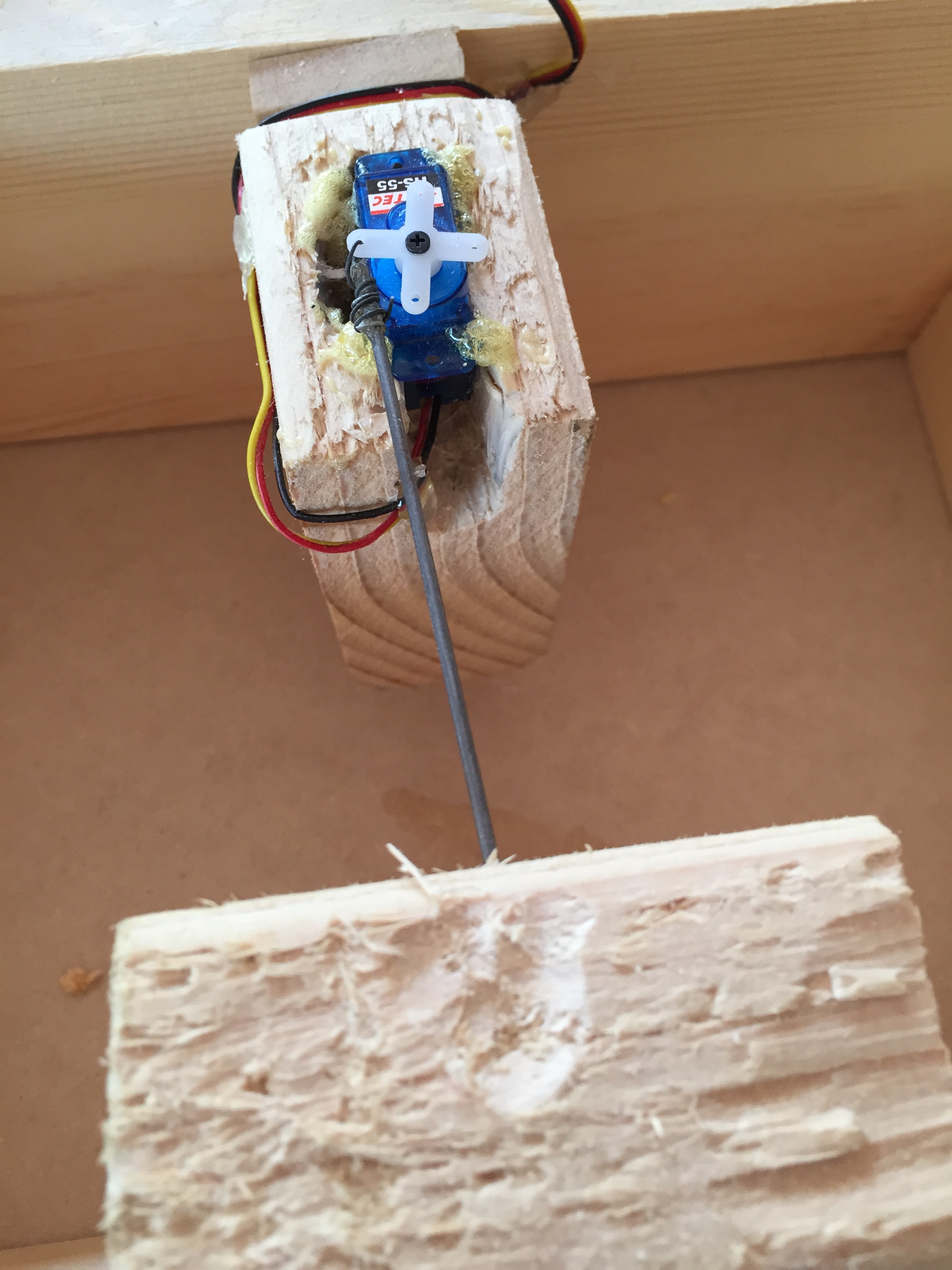
(Here is a closeup of the servo and the pin used to lock the top of the case shut.)
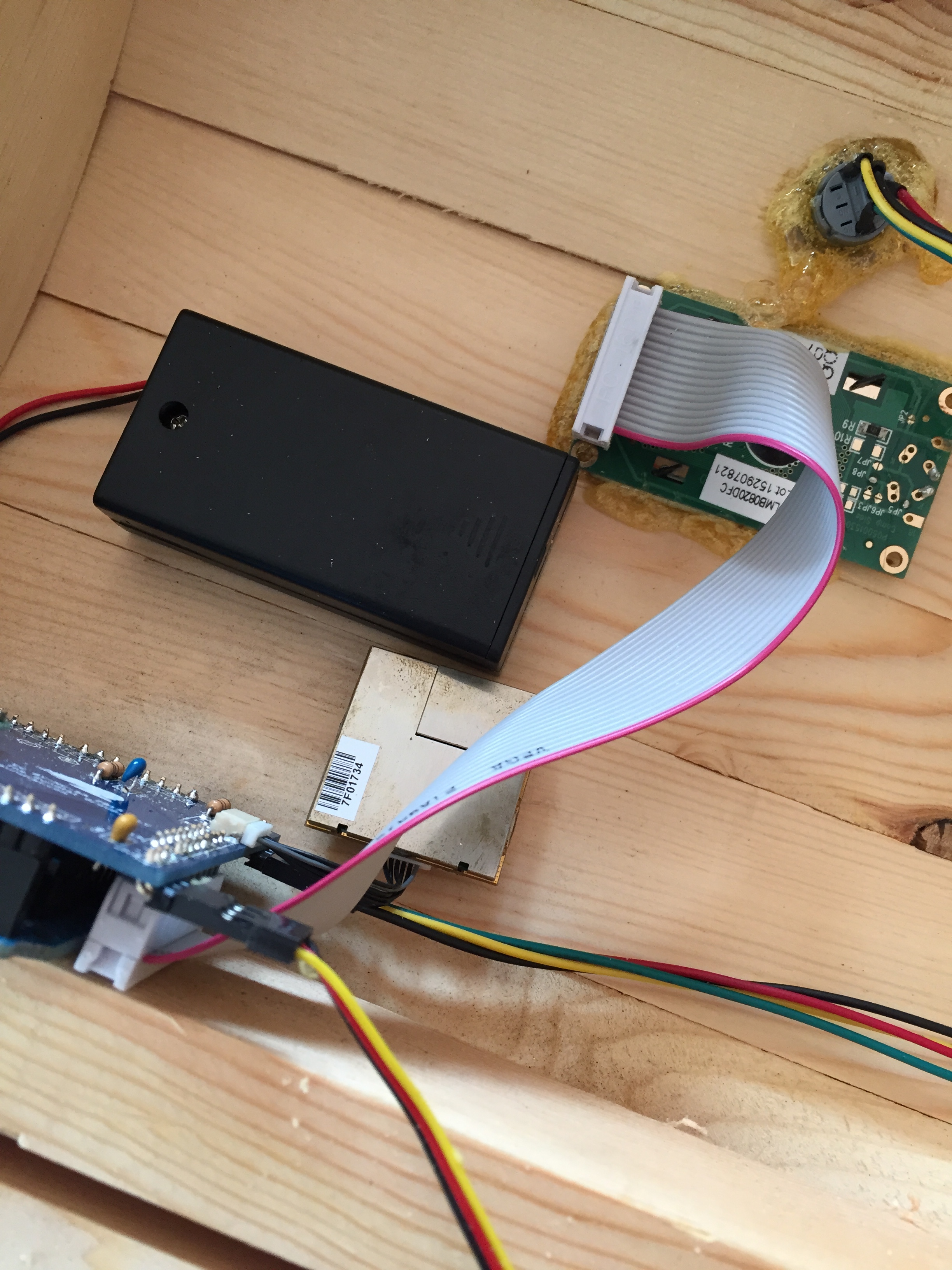
(Here is all the hardware minus the servo. Bottom left blue thing is the Arduino w/ shield, above that and slightly to the left is the GPS module, above that the black rectangle is the battery case and above that the green PCB with the ribbon cable is the 16×2 LCD and above that is the blue backlit button.)
Solar Powered Phone Charger
Hi,
This was one of my more involved projects, taking about three months from original design idea to 10 finished products. This was a challenging project because it required not only making everything work, and work well, but it also required using parts and building it small enough it fit into an Altoids tin. After seeing a video on YouTube where someone built a solar powered phone charger from a small (5″ x 5″) solar panel and a battery powered USB charger, I decided I wanted to build something similar. The original design was just too bulky for me and caring around a box about the size of a tissue box seemed like a dumb idea, so I borrowed the Altoids tin idea from an entry in Make Magazine, where they built a “Mint Tin Amp” audio amplifier.
Batteries would be a good idea too, and after trying out some AAAs I decided they didn’t have enough storage capacity for me. Each AAA battery had a capacity of approx. 850 mAh so 850 x 2 is 1700 mAh total. Mili Amp Hours isn’t the best unit for dealing with this stuff so I converted mAh to Wh (Watt Hours) using an average voltage on the batteries of 1.1v (which is generous). We know that watt-hours = milliamp hours × volts / 1000 so 1700 mAh x 1.1v /1000 = 1.87 Wh. Not a whole lot. According to Wikipedia (The most trusted free encyclopedia 😉 the battery storage of an iPhone 5/s/c is 5.45 Wh. The magic goal here is to provide a full charge to an iPhone. Online, I found some beastly 3000 mAh rechargeable AAs. (They can be found here: http://www.ebay.com/itm/12x-Rechargeable-AA-3000mAh-1-2-V-Ni-MH-battery-BTY-cell-for-MP3-RC-Toys-Camera-/121426504174) Recalculating the storage of the new batteries gives us 6.6 Wh! Thats more then enough to fully recharge an iPhone 5/s/c.
After sorting out the battery situation, I turned to the solar panels. My requirements were: panels that fit in my tin, panels that were already coated in clear protectant, and lastly their peak voltage had to be above 1.5v. After lots of eBay browsing (eBay is by far the cheapest place for parts like this) I had found the perfect panel. I ordered twenty of them thinking I’d make 20 chargers, and also ordered some zener diodes for battery discharge protection and some pushbuttons.
After that I had to figure how to get the ~1.2v of the battery up to 5v for the phone’s USB charging cable. Again after searching eBay I came across a small prebuilt PCB that offered what I wanted, a simple 1.2v in and 5v regulated power out to a USB port. I ordered them up and when they got here and I tried them out by plugging in phone charging cable, and nothing. At first I thought they were broken, but then after some online research I found out that Apple products need about 2.7v on their data lines in order to even want to charge. The solution was to create a voltage divider with some resistors. I did a lovely job bodgeing the resistors to the charging circuit and low and behold, after that it worked like a charm.
Lastly, I cut holes in the Altoids tin, put electrical tape on the inside of the tin, so as not to short anything out, and started assembling them. The assembly process is quite tedious and takes about two hours per tin from start to finish. I had a great time building them and to recoup the costs of parts, I made extra chargers and sold them at school. People were very impressed with them and they would happily pay $40 for a small emergency phone charger. I made 9 chargers, and when all was said and done, I sold 7 of them and kept two for myself. If I ever want to make 10 more (I bought the parts for them) I could, but spending 20 hours repeatedly building the same thing get very tiering very fast.
In the end it was really fun and I learned lots for this project. I love being able to teach myself by giving myself challenges and then trying to solve them. When all was said and done, I had had a fun two months working on designing, ordering parts, and building this project and I also walked away with an $200 including cost of parts. People came to me telling me to turn this into a business, and it sounds like a great idea until you realize that you have to spend two hours per charger building it. Maybe one day I will turn it into a business and outsource labor and such, but for now, I am really happy that I just had a fun time doing it.
Here are some pictures of the Altoids Phone Charger:
Here is a view from the outside. The red button is the charge button, press it to send power to the USB port.
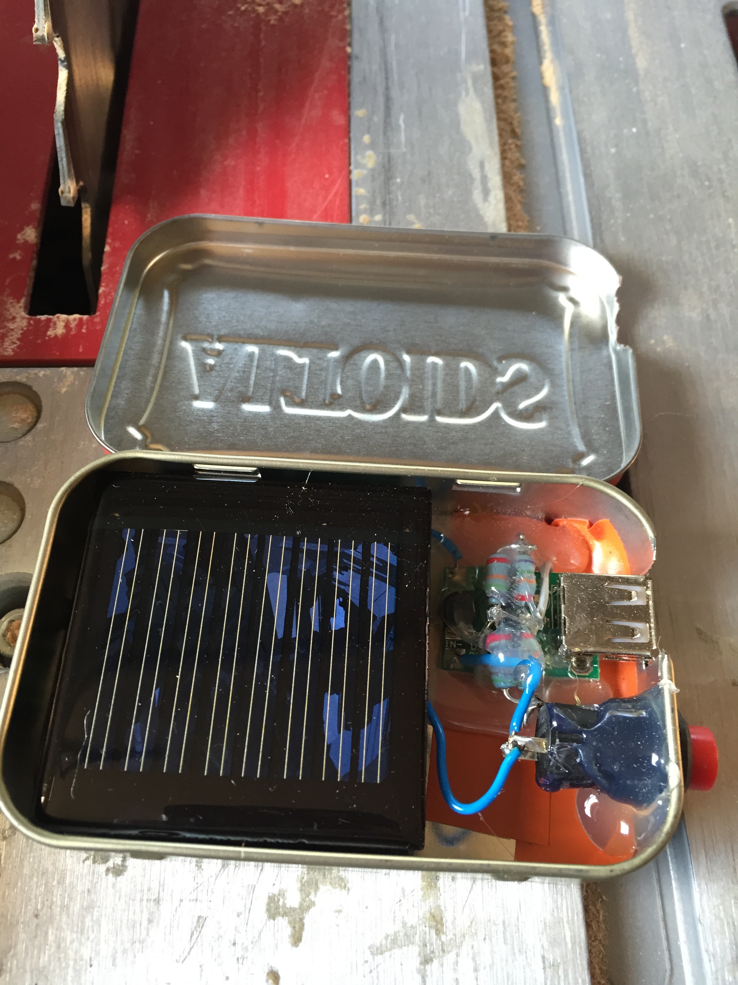
Here is an inside view of the charger. Notice that the solar panel fit just barely into the tin.

Here is a closeup view of the electronics. I used a lot of hot glue to keep everything in place. Notice the resistor voltage divider on top of the USB board. If you look right below the edge of the solar panel you can see the diode soldered directly to the battery.

Here the charger is charging up an iPhone 6. With the iPhone 6’s huge battery, it won’t charge it fully but it comes close. Definitely enough juice to call people in an emergency or find your way home when your lost.
Electronic Slot Game
Hi,
This is part of a series of posts adding old projects that I have done years ago on to my website. Soon everything should resume chronological order.
About 4-5 years ago I saw a post in Make magazine about someone who had come up with some sort of slot game idea. They had a very small article, with about one or two paragraphs of info on this game idea, and I thought it looked interesting.
After a trip to the hardware store and a trip to RadioShack (argh, I know, I still face palm thinking about how I used to use Radio Shack) I had most of the parts. I made the slots in the wood with an normal sheet metal drill bit (the days before I had a jigsaw) and attached the L brackets. Then I wired everything up. I used a two pole six position rotary switch (RS still sells them here http://www.radioshack.com/radioshack-2-pole-6-position-rotary-switch/2750034.html) and wired up six different winning combinations. (If you look at the picture below, you’ll see I used magnet wire to make all the connections… ugh, If only I had known) I finished up by painting the wood blue and yellow and added a couple of LED’s and a switch.
So, here’s how you play the game:
You bet four quarters ($1) and place them between the L brackets. This completes part of a circuit, once you have placed all four quarters, you flip the switch and if the red LED lights, you loose. If the green one lights, you win and get $100. (The odds are of course in the house’s favor.) The rotary switch allows you to select between six preset combinations, that way if one person wins, the next person doesn’t copy their pattern.
Here are some pictures:
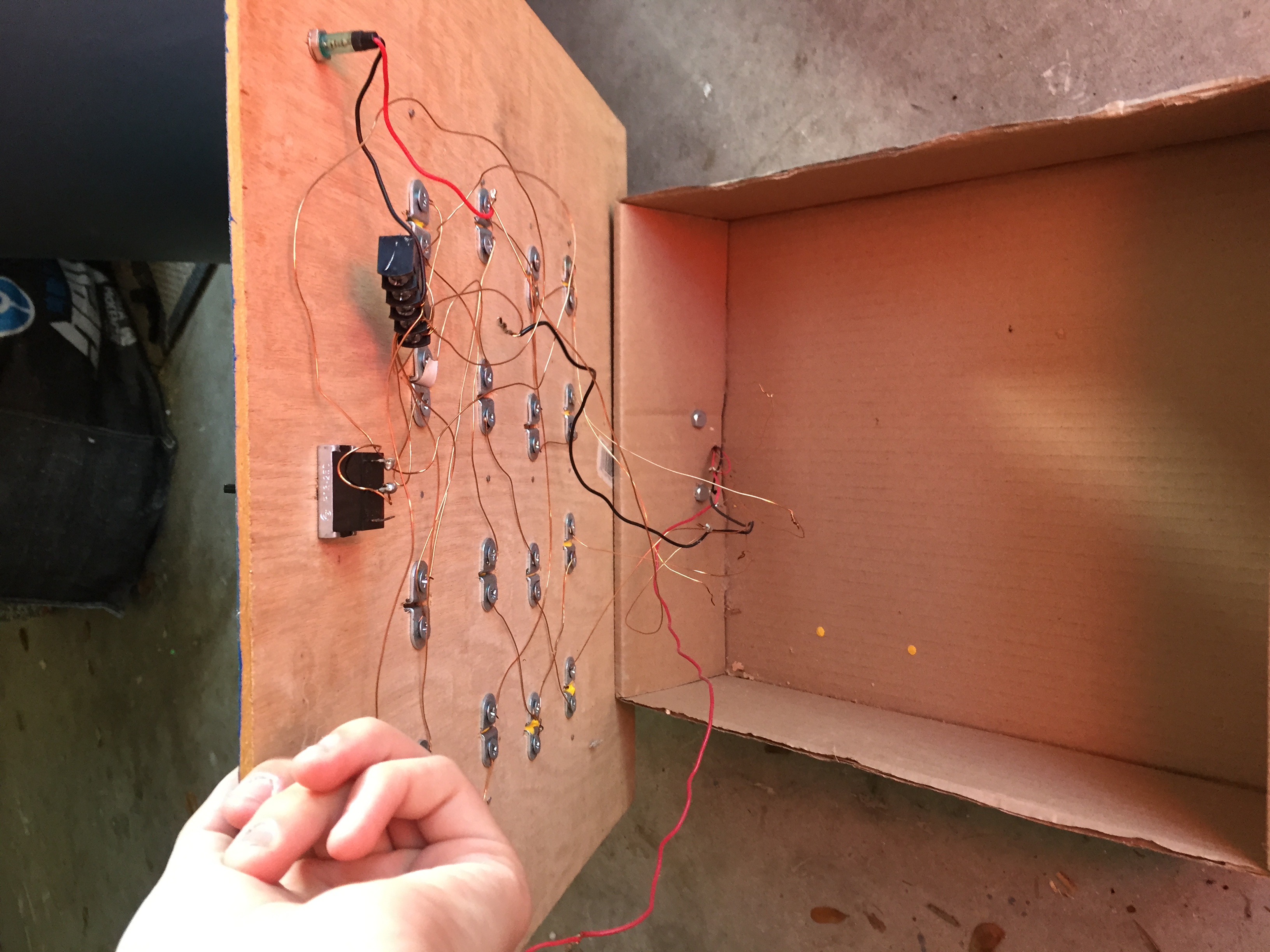
(View of inside wiring)
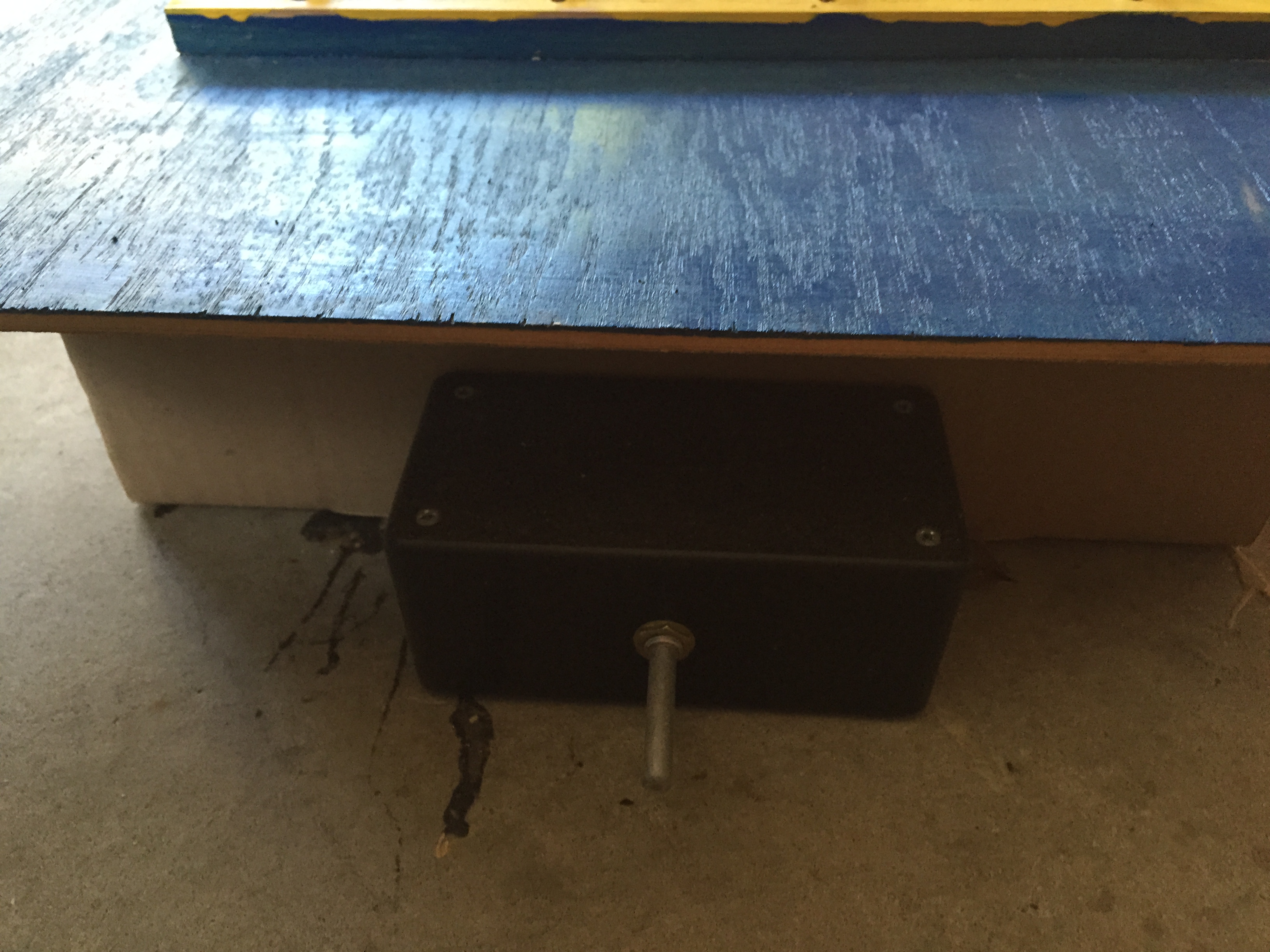
(Rotary switch box)
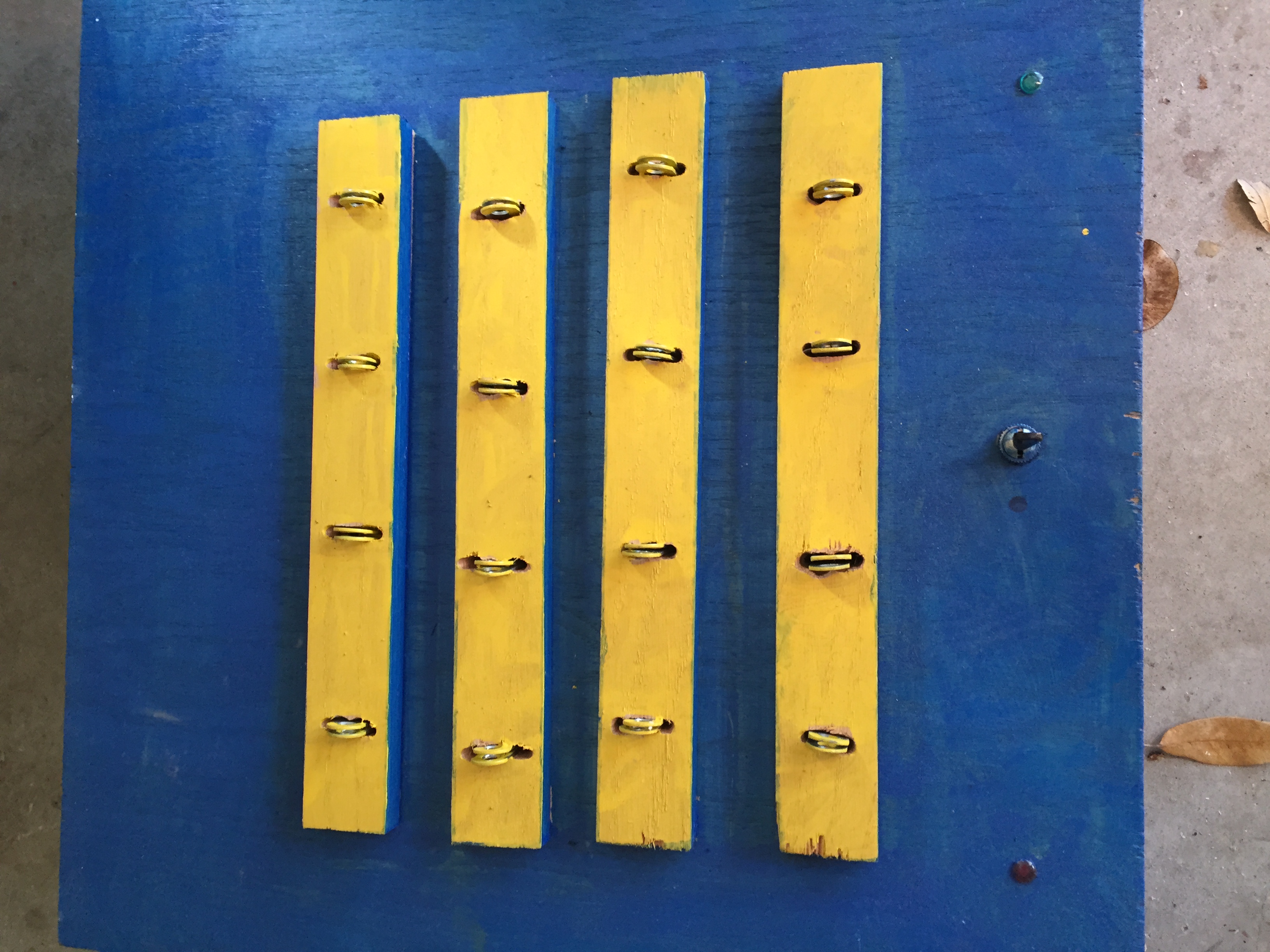
(Top view, quarters go in between those brackets)
My First Trebuchet
Hi,
I made this trebuchet about two years ago for a history class project. We were learning about the Middle Ages and we had to do a project and I suggested that I build a trebuchet for the medieval siege weapons topic. I built this with limited tools (I had no table saw at the time) and limited time (about a week), but I think it came out pretty nice. I shot an old hard drive, weighing about a kilogram (2.2 lbs) fifty feet. I used a 25kg (~50 lbs) counterweight. The hard drive shot 20m (60ft) which I thought was quite impressive. I made this video using iMovie, back in the good old days when I was just learning Final Cut Pro.
(I made this video soooo long ago) 😛
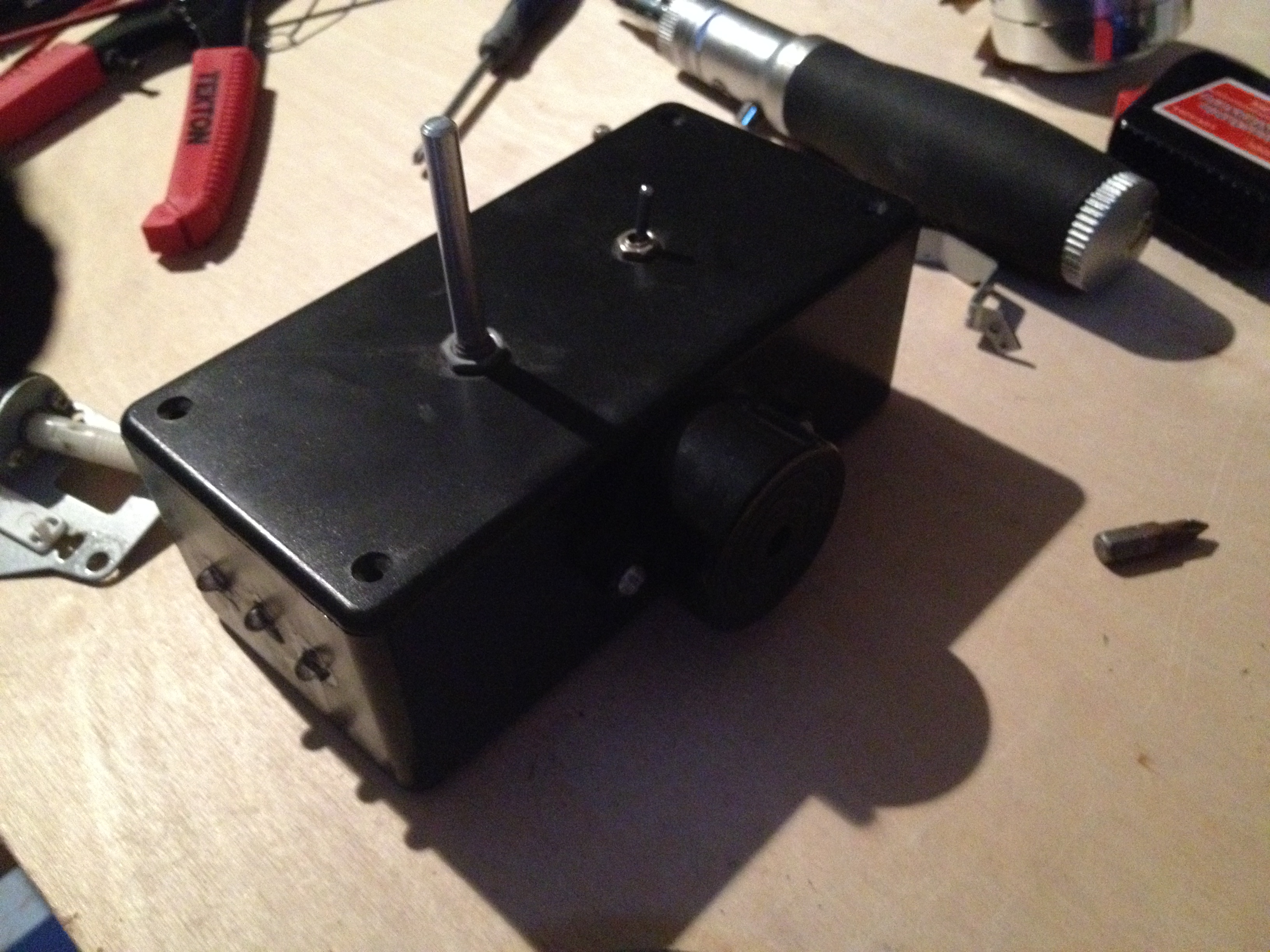
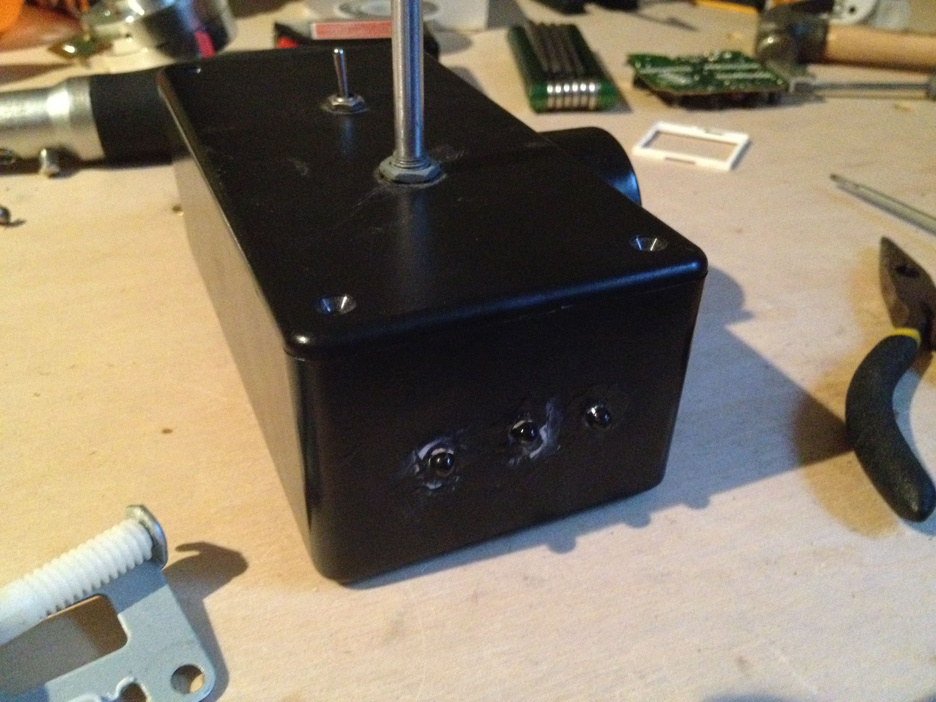
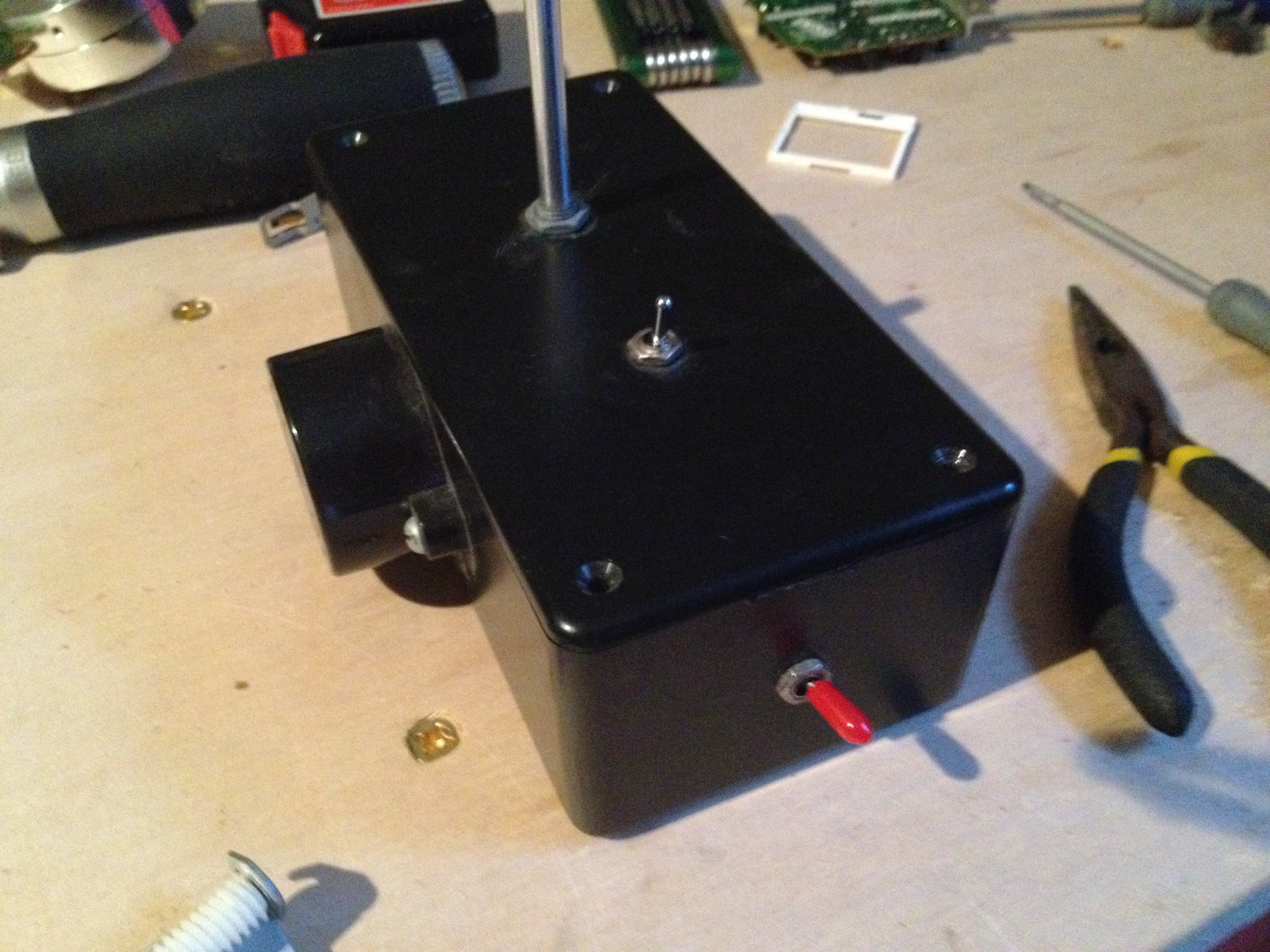
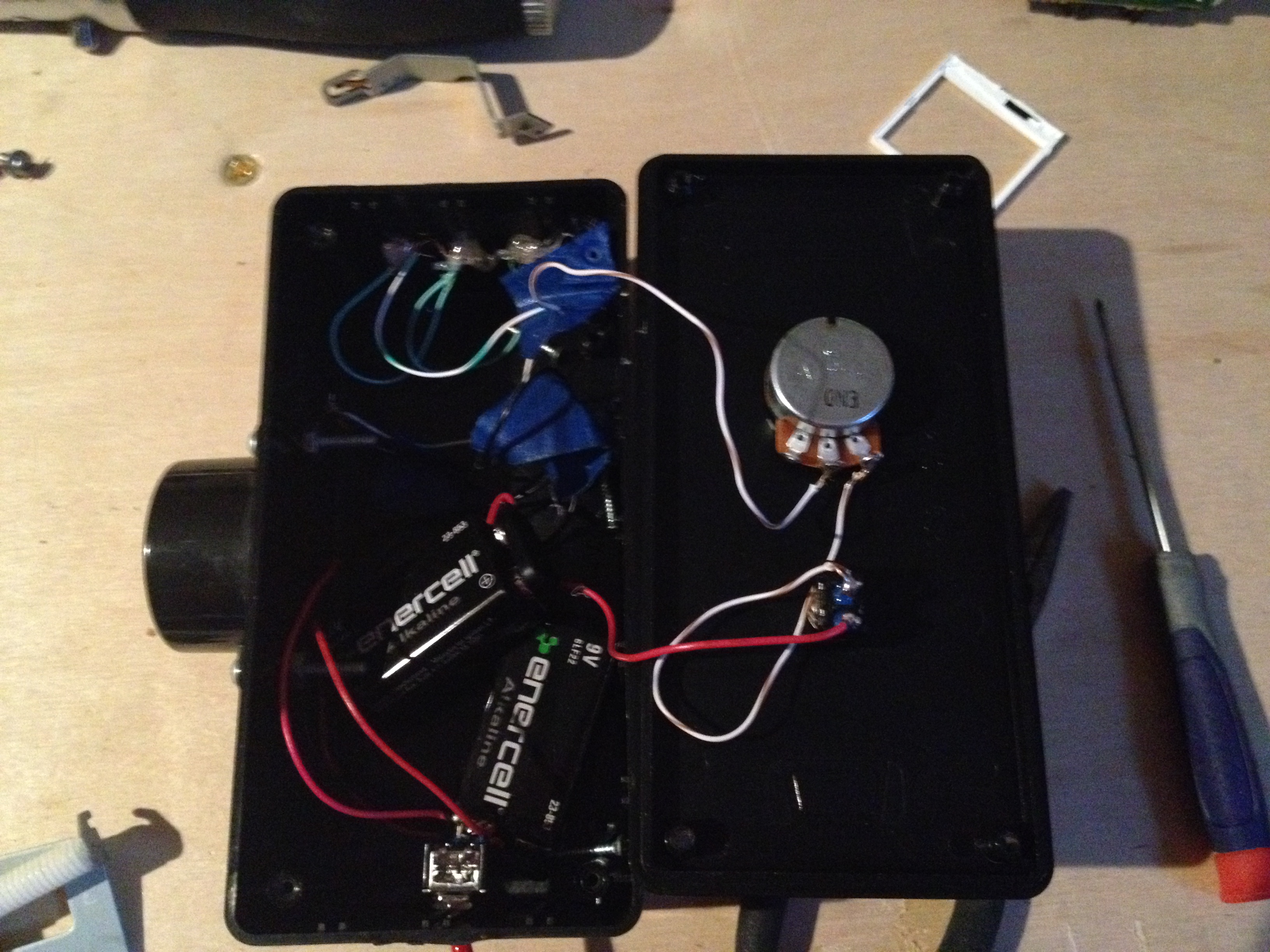
Dimmable Flashlight/Warning Device
This was the project that started it all. I made this before I knew about resistors and ohms law :p I made this about 5 years ago when I was about 10 years old as my first project with my soldering iron. The flashlight circuit is basically a switch and a 9v battery and a potentiometer and 3 LED’s. About a year after I had built this, after I had learned about resistance and how leds need a current limit resistor, I went back and found the led package and figured out that the 3 leds in series each had a forward voltage of 2.8v. 2.8 x 3 is 8.4v, I was just lucky 😉 The alarm circuit is a 9v battery with a switch and a piezo alarm. Here are some pictures: